XR to VESC: A Onewheel Conversion Guide
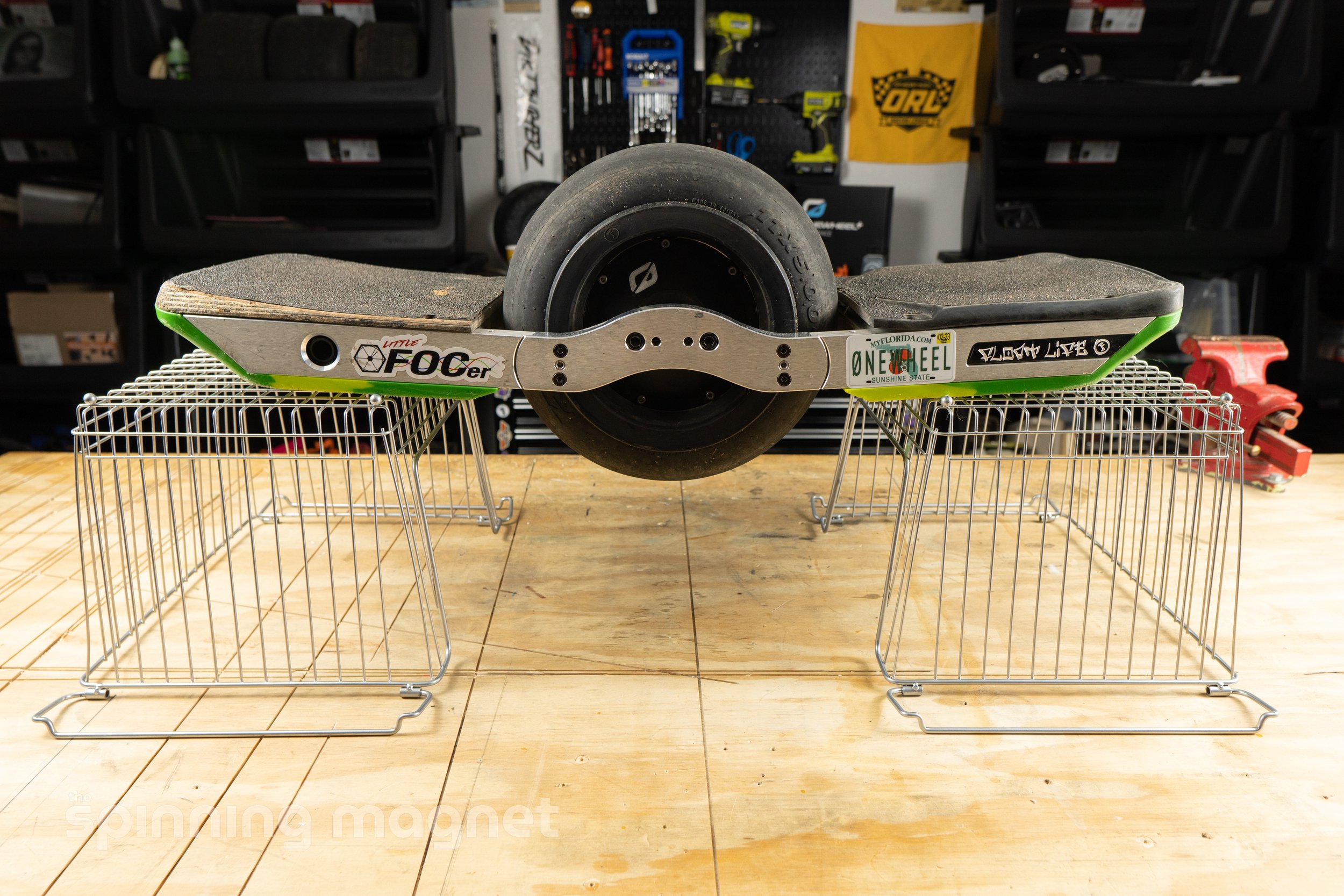
Onewheel+ XR with Little FOCer 3.1 VESC conversion
Contents
-
-
-
-
-
-
Speed Measurement
Ride stiffness / Responsiveness
Braking
Turning
-
I can’t connect my desktop to the Wireless Bridge.
My desktop is connected to the Wireless Bridge, but it keeps disconnecting.
What is this sound?
My phone keeps disconnecting from the VESC’s Bluetooth.
-
OWIE for Battery Cell Monitoring
Flipsky Bluetooth Module
-
How waterproof is this thing?
How much range will I get?
What’s the top speed?
-
Putting together this guide was a ton of work, so if you find it valuable, please consider buying me a coffee or purchasing some merch! Thanks 🤙
If you think I should’ve done something differently or you have a suggestion, keep it to yourself.
Just kidding! Shoot me an email with any questions or suggestions: tk@spinningmag.net.
Or find me on Instragram: @tkgarrett.
Any time you see a highlighted term, it can be found in the glossary at the bottom of this guide.
Introduction
Open-source is quickly moving from the future of onewheeling and into the present. Pro riders are beginning to adopt the VESC platform, which continues to evolve at a rapid pace. This year, we will see multiple open class races that will have no restrictions placed on the manufacturer of the boards that are ridden. The configurabilty, customization, and raw power are huge draw towards VESC, but because of it’s open-source and DIY nature, it remains inaccessible to many. There is currently a need for more clear documentation, so I’ve written this as a start-to-finish guide on how to get up and running on your own VESC based onewheel. This will include photos or screenshots for each step, as well as wiring diagrams. I plan on updating this guide over time, but that may prove impossible or futile as VESC evolves.
Project Goals
The aim of this guide is to convert a Onewheel+ XR to use an open-sourced VESC based controller mounted in a 3D printed controller box. All other Future Motion components will be re-used, including the stock BMS, battery, and wiring harness. If at any time after the conversion you want to switch back, it will be as simple as reinstalling and connecting the old Future Motion controller module. This guide will also cover the initial VESC software setup, configuration, and some common troubleshooting steps. By the end of this project, you’ll have not only a working board, but the knowledge to continue exploring the world of DIY PEVs and electronics. If all of your ducks are in a row, you can easily complete this in a weekend. After doing a few myself, XR to VESC conversions only take me a few hours.
Standing on the Shoulders of Giants
When I built my first board, I didn’t know very much at all about electronics, battery safety, or PID tuning. Where relevant, I’ll include links to other content creators that are way smarter than me. But, to say thanks, here is a short list of VESC onewheel titans that should definitely be at the top of this guide:
Mitch Lustig - Creator of the VESC balance app, without which none of this would have been possible.
Surfdado - Developer of Adaptive Terrain Response (ATR), the Float Control app, and many other balance app refinements.
Nico Aleman - Developer of the VESC Float package, which is heavily based on surfdado’s work.
The communities on pev.dev, Discord, and Facebook that patiently answer all of our dumb questions.
Disclaimer & Warnings
It should go without saying, but riding a one-wheeled electronic balance board is dangerous. And riding a DIY, self-built onewheel? Even more so. If you miswire something, you could start a fire or fry your hardware. If you misconfigure something on your board, it could result in a crash involving cuts, scrapes, bruises, broken bones, or possibly even death. The procedures outlined in this guide aren’t difficult, but they require patience and attention to detail.
A Warning About the BMS
This particular hardware configuration re-uses the Future Motion BMS. The BMS has the ability to cut power to the board to protect the battery and in certain situations, this could happen without warning. These situations are mostly caused by hardware failure or austere conditions, such as:
A bad cell in the battery
Extreme cold weather
A damaged wiring harness
So, why re-use the BMS?
The BMS provides the critical function of keeping your battery cells balanced. If your battery cells are unbalanced, your battery could overcharge and catch fire while charging. There are a couple of other added benefits. They are:
If the board sits idle for ~20 minutes, it will turn off automatically. This prevents the battery from draining.
The Future Motion controller module is still 100% compatible with the rest of the board. If for any reason you ever want to swap back, you can.
Mitigations and Accepted Risk
There are some ways to mitigate the risks associated with this setup:
Don’t ride in freezing weather. Lithium batteries are dangerous below freezing, so the BMS can cut power if the battery gets too cold.
Install an OWIE chip to monitor the battery cells manually. I will cover this with my own guide at a later time, but if you are interested in it now, check out this conversation on pev.dev.
Check your wiring harness and other components regularly for damage.
Always wear a helmet and other safety gear.
These mitigations don’t completely solve the problems associated with running the stock BMS. At the end of the day, you will need to decide if you accept the risk that at some point your board could shut off while you are riding it. But even completely stock XRs and GTs have been reported to cut off during operation, so this risk is probably one you’ve already accepted. I don’t mean to dissuade anyone from building a VESC onewheel, but if these sound like risks that you don’t want to take on, this may not be the project for you. Proceed at your own risk.
Before We Get Started
I’ve included purchase links to any hardware or tools you will need. Where appropriate, I’ve included affiliate links, which will earn us a small commission.
Knowledge
To successfully complete this conversion, you should have the following pre-requisite knowledge or at least be willing to learn:
How to disassemble and reassemble your Onewheel+ XR - I’d recommend watching this video from 1wheelParts.
How to use a multimeter - To check polarity, voltage, and continuity of your battery.
How to solder wires and connectors - We will need to solder in the power button and charging port so that they are compatible with the Future Motion BMS.
How to install heat set inserts - These are the brass inserts that will be pressed into the controller box. Read about them below.
Hardware
Before beginning, be sure to have on hand:
Onewheel+ XR with a working BMS - Hardware version and firmware version are irrelevant, it just needs to be an XR. Aftermarket accessories such as footpads, bumpers, rails, and tires will have little relevancy in this guide, so those should be fine. If you have an upgraded battery, such as a CBXR or a JWXR, this is also acceptable and will be addressed during the software setup. Your Onewheel should still have a working BMS. If your goal is to bypass the BMS, this is not recommended and this is not the guide for you.
Little FOCer VESC and connector kit - This is the VESC controller and most of the necessary bits and bobs to make it compatible with your current Onewheel.
North America - Flowglider DIY Bundle from MakersPEV.
Europe - Little FOCer V3.1 VESC 84V 20S Complete Kit from CustomWheel.
Power button - The Future Motion BMS isn’t compatible with the latching button that comes with the DIY bundle, so we need purchase this separately. This is the one I used for my build.
Controller enclosure - 3D printed Flowglider box. I print my own now, but I’ve had good experience with Phillip at Lit Timber. Get the PA6-CF (nylon with carbon fiber) version if you’re worried about heat resistance. PLA can melt or warp in a hot car.
Controller enclosure lid - Lit Timber carries this sometimes as well. But its the same product. Choose the regular version, not the lid mount.
Smart Phone and Computer
iPhone or Android mobile phone - to facilitate the Bluetooth connection from your VESC to your desktop/laptop
Desktop or laptop computer (Windows, Mac, or Linux) - to perform the initial setup and calibration
Note: Due to a bug with the iPhone version of VESC Tool, I am only including desktop/laptop documentation at this time. However, if you only have an Android device and still wish to convert your board following this guide, it is definitely possible. The interface on mobile is laid out differently than the desktop version, but all of the necessary menus are present. The iPhone bug affects the VESC Packages section of the app, which is necessary to complete the setup. You will still need a mobile device so your desktop can to connect to your VESC through Bluetooth and either an iPhone or Android may be used for that. You just can’t use the iPhone for the full setup without a desktop computer as well.
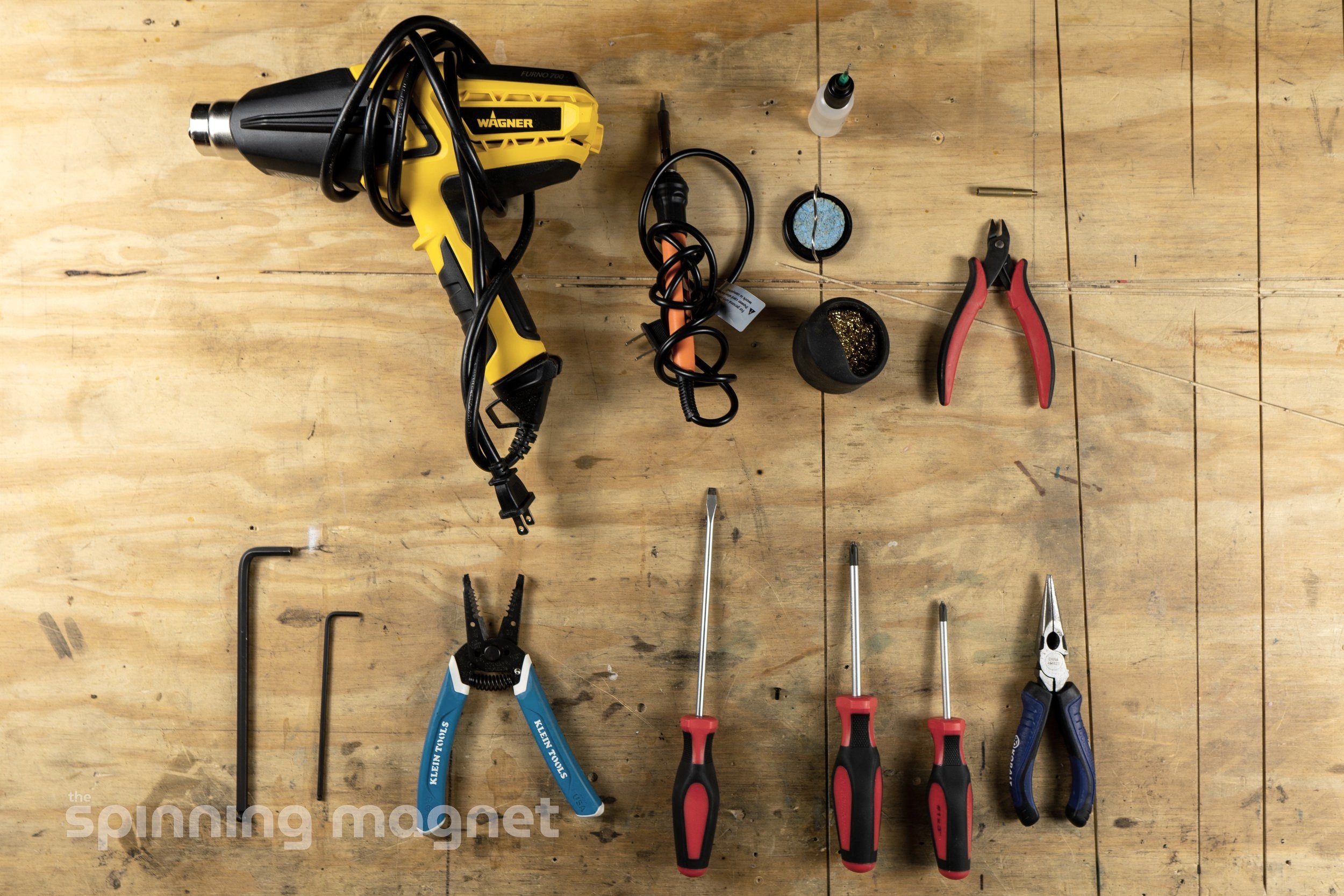
Tools
You probably have most of these tools already, but I’ve included some Amazon links just in case. Please note, unless they are marked with an asterisk (*), I haven’t personally used these tools.
Screwdrivers (#1 Phillips, #2 Phillips, Flat Head)
Soldering Iron Kit (including solder, flux, and helping hands)
Optional
Adhesive Backed Fishpaper * - Insulative material to help prevent electrical shorts.
Extra Thermal Pads * - When you eventually need to take your controller apart to fix/change something, these will be good to have on hand. I always have at least one on hand.
Zip Ties - Good for cable management.
Hot Glue Gun - To keep the controller and wires in place during assembly.
Flowglider Connector Cover * - You can reuse the XR connector cover, but this one is way better.
Heat gun * - Used to shrink the heat shrink. You can use a lighter, but a heat gun is MUCH easier. There are cheaper versions, but this one has variable temperature and works great for me.
Helping Hands * - To hold your wires and connectors in place while you solder.
JST Connector Kit * - This is great to have on hand in case you accidentally break a connector included in the DIY bundle.
*Products that I personally use and recommend
And if you wanted to replicate my build entirely, you’ll need a few more things:
Cost
The cost of this project will greatly depend on what parts you already have, but here is an estimation of the very basics. (You never include new tools in the project cost 🤣)
| Item | Price | Notes |
| Onewheel+ XR | $ 1,250.00 | A used XR will run you around $1000 - $1500 if you don't already have one. |
| Little FOCer VESC and connector kit | $ 430.00 | |
| Power button | $ 11.49 | |
| Controller enclosure | $ 99.00 | PA6-CF version |
| Controller enclosure lid | $ 45.00 | |
| Total | $1,835.49 |
Hardware Setup
Alright, now that you have a pile of parts and some shiny new tools, let’s dive in to the build. I’m consolidating information from a couple of different sources, which are listed at the bottom of the Hardware Setup section.
Wiring Diagrams
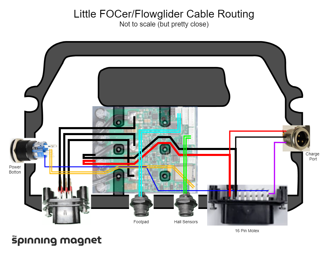
Pictured above is the wiring diagram that we will be replicating. It is a modified version of sav0’s diagram from their post on pev.dev. It has been modified to include the purple wire, which will allow the board to turn on when connected to a charger and will also enable cell balancing. There are many different ways to configure the hardware in a VESC build. I’ve opted for this version because it doesn’t break compatibility with the stock Future Motion controller and it allows the BMS to balance the battery cells. If, at any time, you want to un-VESC your onewheel, you will simply need to re-install the original controller module.
Installation
Let’s finally put some stuff in the controller box and get it installed. In some of the photos, a grey controller box was used. I ended up swapping over to a black PA6-CF box after my old grey ASA box broke. I tried to capture all of the necessary photos from the swap, but I missed a few.
Jump directly to each step:
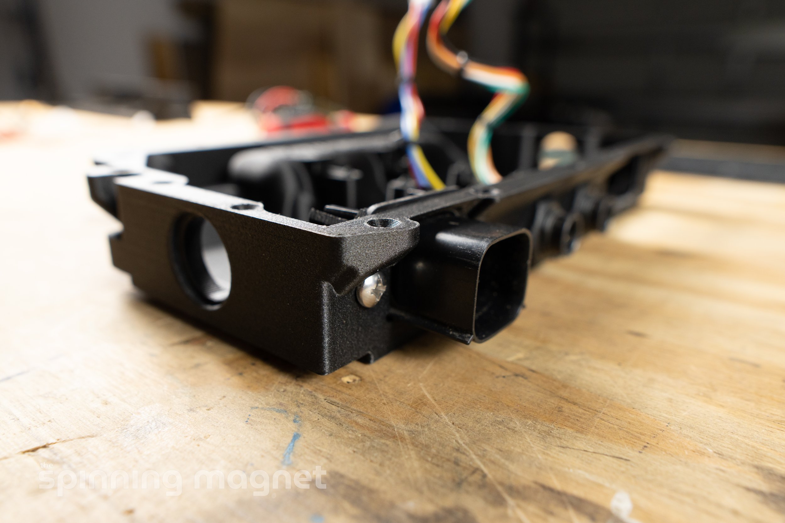
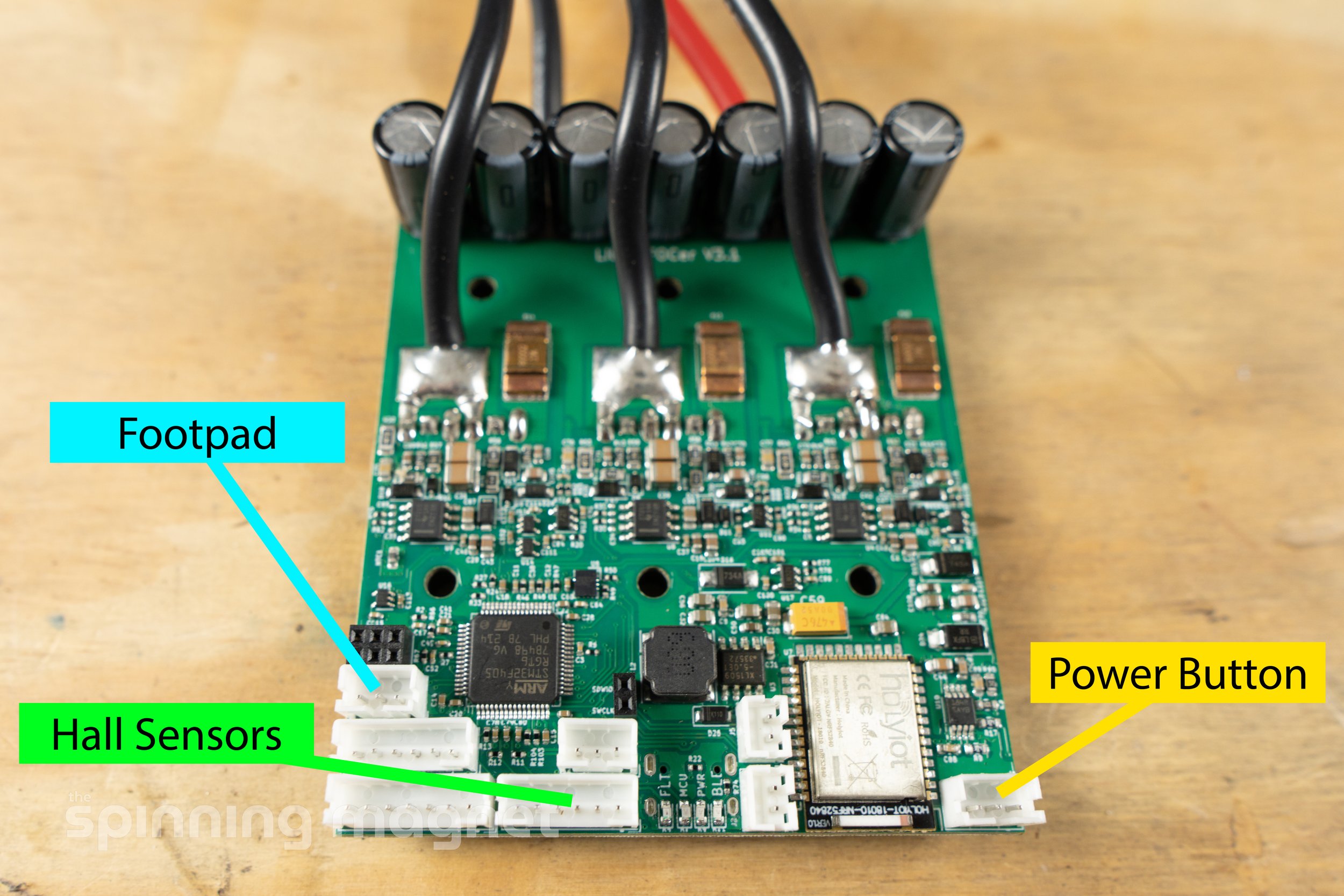
1. Install the footpad and hall sensor Switchcraft connectors.


Switchcraft is in the glossary
a. Install the 3-wire footpad connector on the left and the 5-wire hall sensor connector on the right to mimic Future Motion’s configuration. Or, swap the connectors so that the hall sensor is closer to the motor power connector, which I think makes more sense.
b. Make sure to install the gaskets on the inside of the box.
c. Snug down the plastic retainer nuts using an adjustable wrench. Be careful not to over-tighten! Plastic threads are easily stripped.
TIPS
You may need to use a rasp, file, or small knife to widen the hole before inserting your connector because 3D printer accuracy will vary.
Install small zip ties to help with cable management. Be sure to trim down the zip ties so that they are flush with the head. You don’t want any sharp edges exposed that could cut the other wires inside the box.
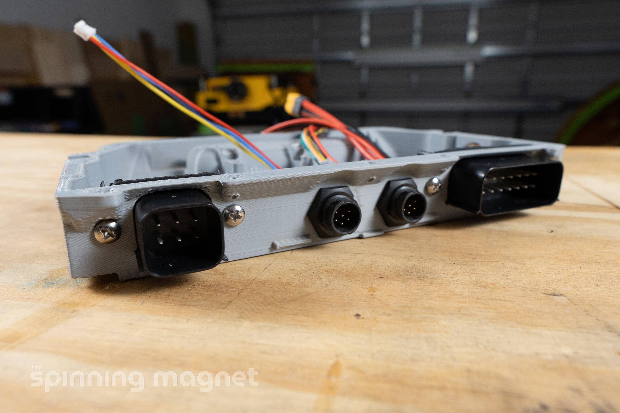
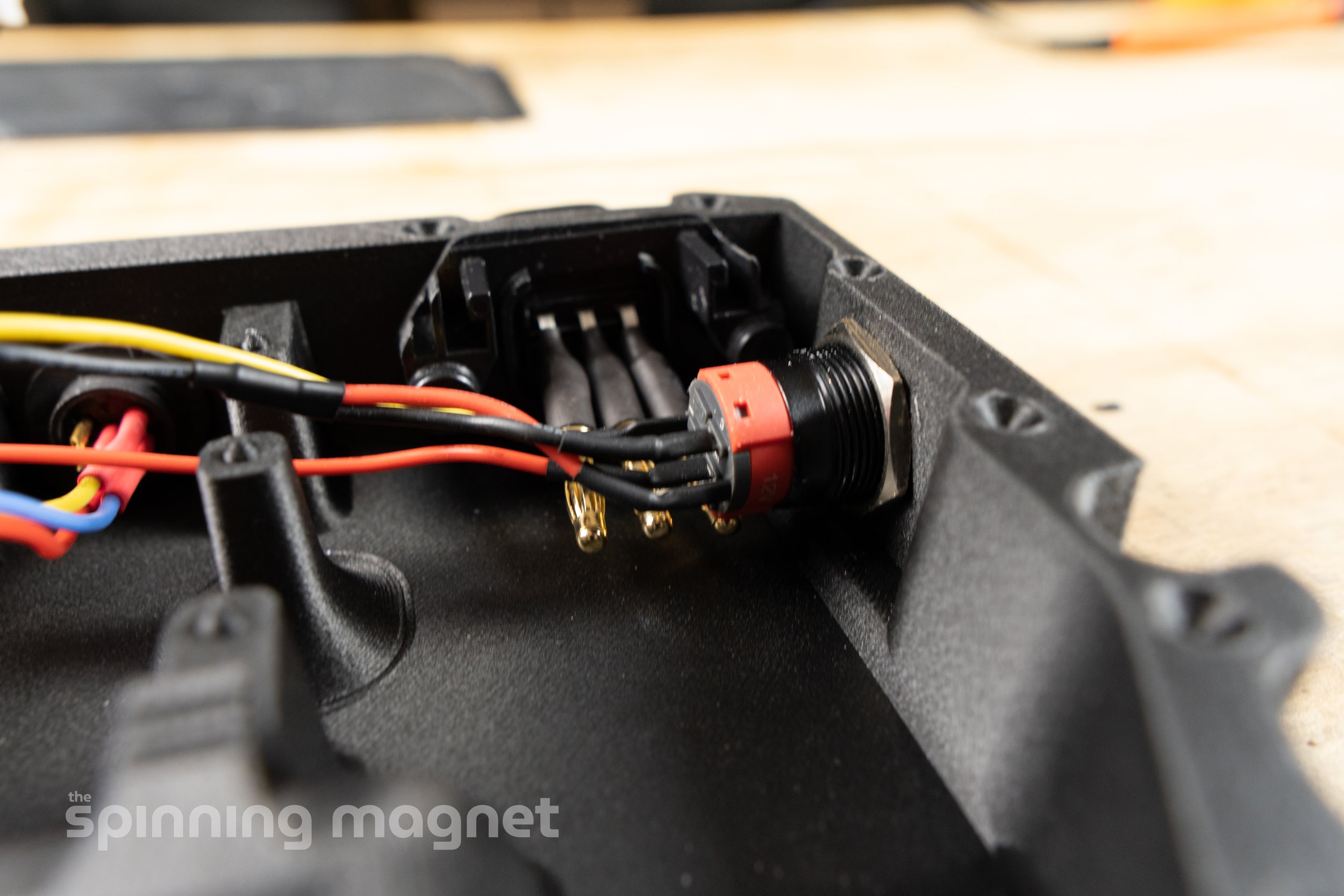
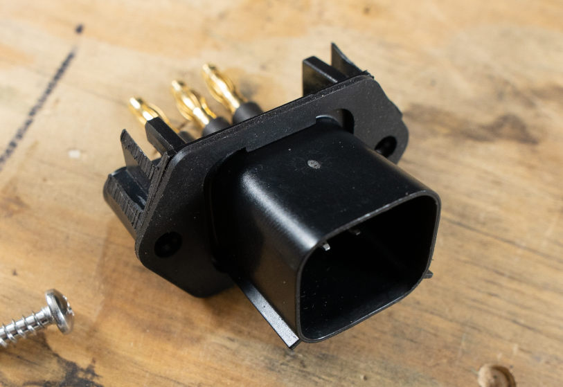
2. Install the 6-pin motor power Molex connector.


Molex is in the glossary
a. You’ll need to bend the gold bullet connectors down slightly so that there will be room for the power button. Be careful when doing this, as you don’t want any of the 6 pins that they are attached to to pull through the plastic.
b. Slide the connector into its slot.
c. Make sure the gasket is on the inside of the box.
d. Install the screws with a #2 phillips head screwdriver. Take care not to overtighten. You can damage the 3D printed controller box if you the screws are tightened too much.
3. Install the 16-pin battery power Molex connector.


a. Slide the connector into its slot.
b. Make sure the gasket is on the inside of the box.
c. Install the screws with a #2 phillips head screwdriver. Take care not to overtighten. You can damage the 3D printed controller box if you the screws are tightened too much.
4. Solder a wire to the XLR charging port.


This is the wire that will be connected to the purple wire in a subsequent step. So, if you have purple wire, use that instead. I didn’t have any on hand.
a. I used a 20 AWG silicone wire ~4-6 inches in length. It will get trimmed down to just a couple of inches later, but it’s nice to have extra length for heat dissipation while soldering.
b. Heat up the XLR solder cup and melt in enough solder to fill it up. Work quickly, as you don’t want to melt the connector.
c. Solder in the silicone wire and then cover it with heat shrink.
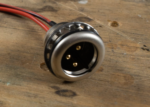
5. Install the XLR charging port.


XLR is in the glossary
a. Slide the connector into its slot.
b. The rubber o-ring should be on the outside of the box.
c. Install the toothed washer and then the metal retaining nut.
d. Tighten the retaining nut with needle nose pliers. This isn’t really the best tool for the job, as they will want to slip, but it’s hard to get anything else in there. Take care not to over tighten.
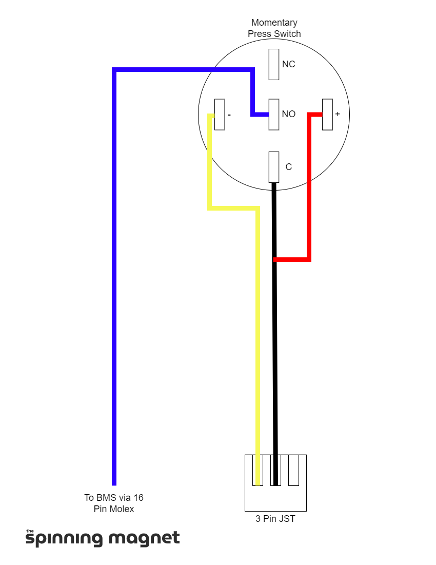
6. Solder the momentary press power button.
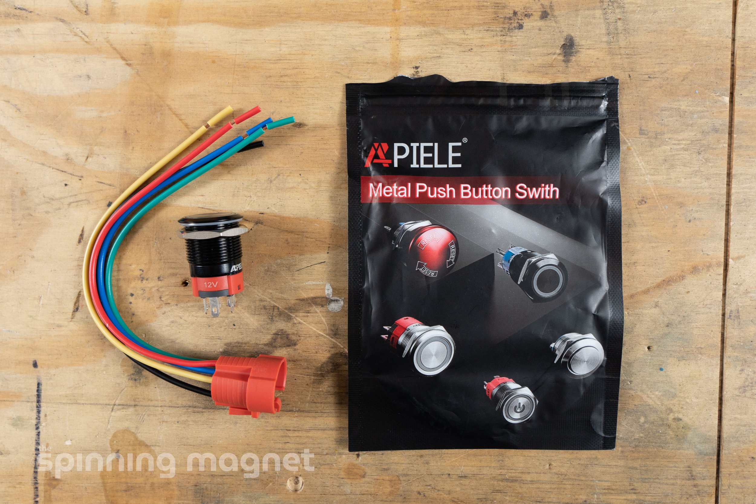


In this step we will set up the momentary press switch by re-using the wiring from the latching switch that was included in the DIY bundle.
a. Discard the red wiring connector that was packaged with the momentary press switch. Unfortunately, there isn’t enough room to use it.
b. On the latching switch that was included in the DIY bundle, carefully snip away the wires. You’ll want to snip as close to the switch posts as possible.
c. Remove the red wire from the white JST connector. This can be done by carefully lifting the retainer tab on the JST connector and pulling out the wire. Video demonstration here.
d. Solder the wires according to the pictures and wiring diagram above. Don’t forget the heat shrink!
7. Install the power button.
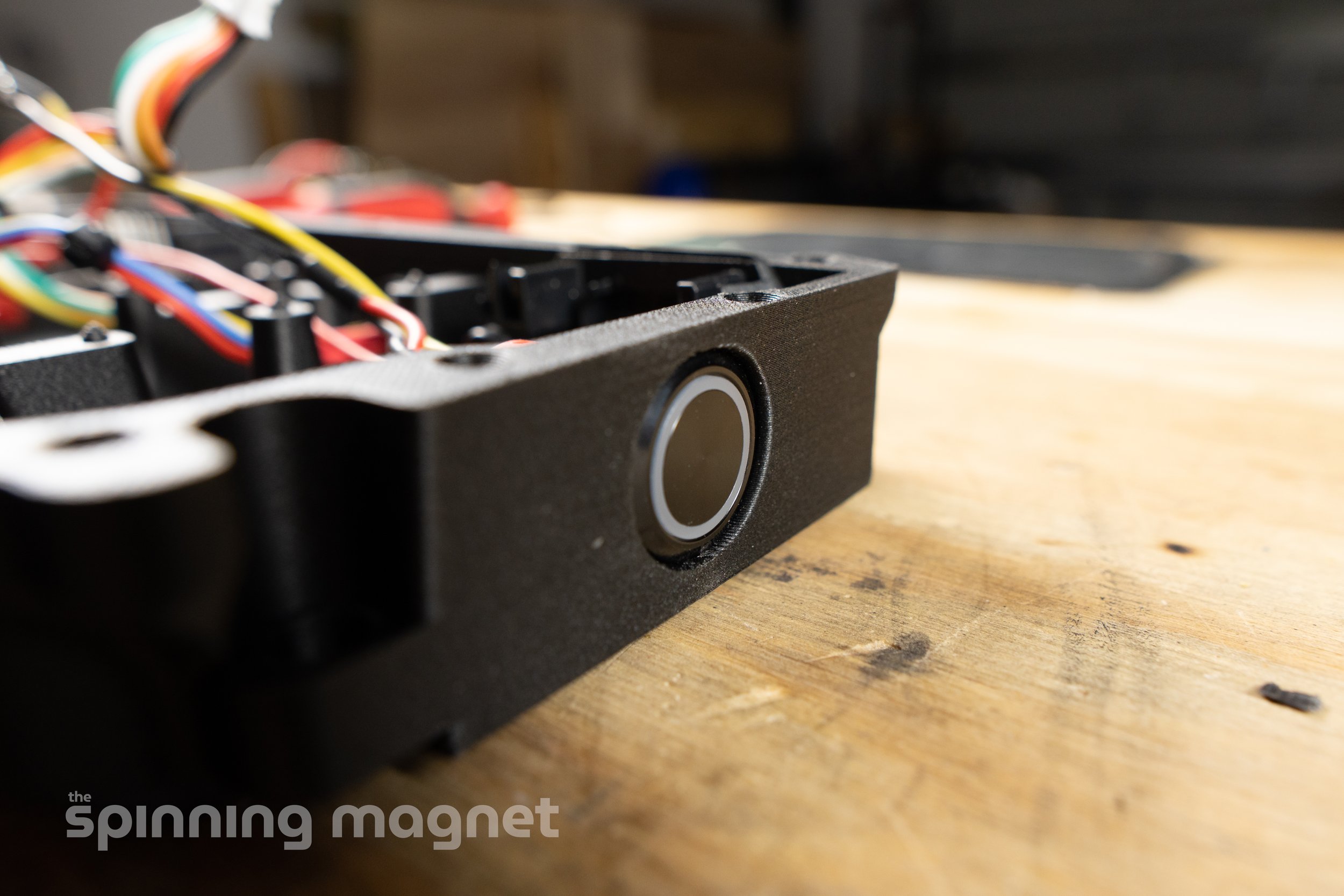
a. Slide the power button into its slot.
b. The rubber o-ring should be on the outside of the box.
c. Tighten the retaining nut with needle nose pliers. This isn’t really the best tool for the job, as they will want to slip, but it’s hard to get anything else in there. Take care not to over tighten.
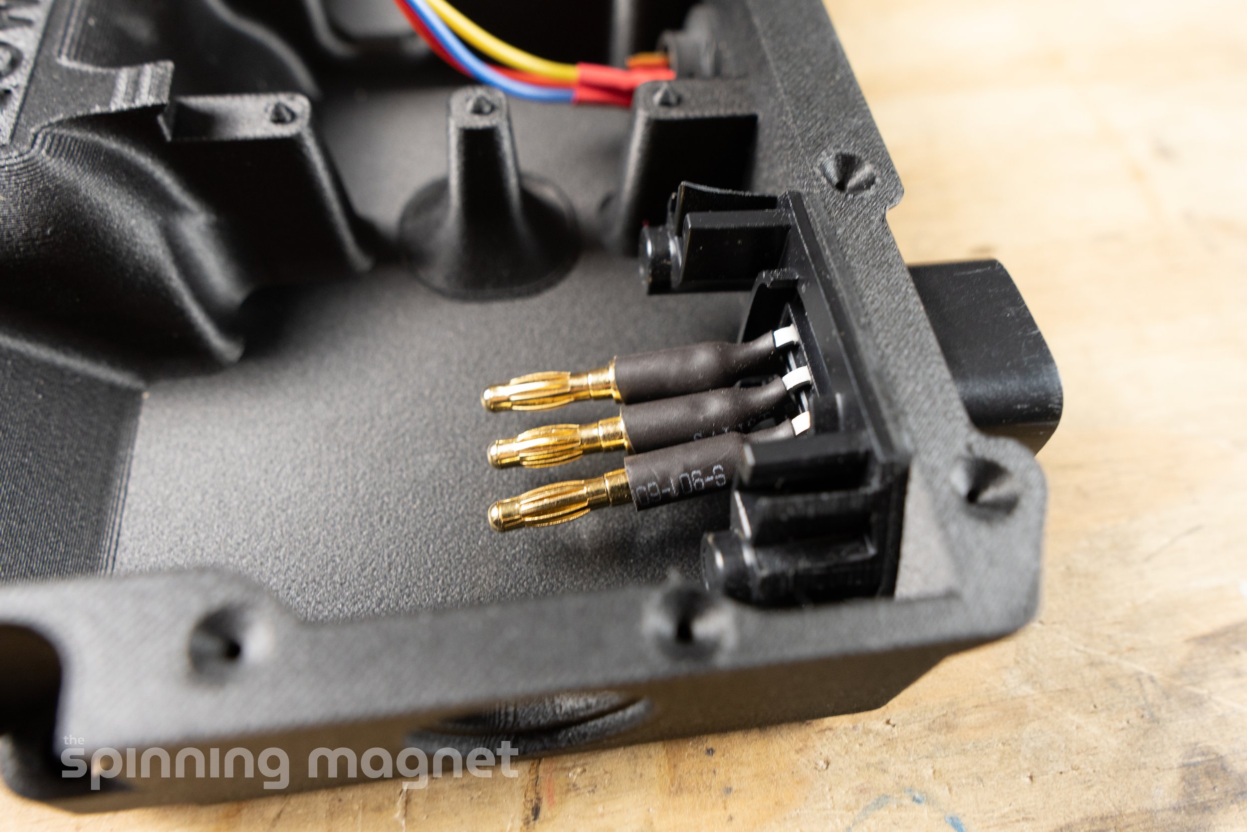
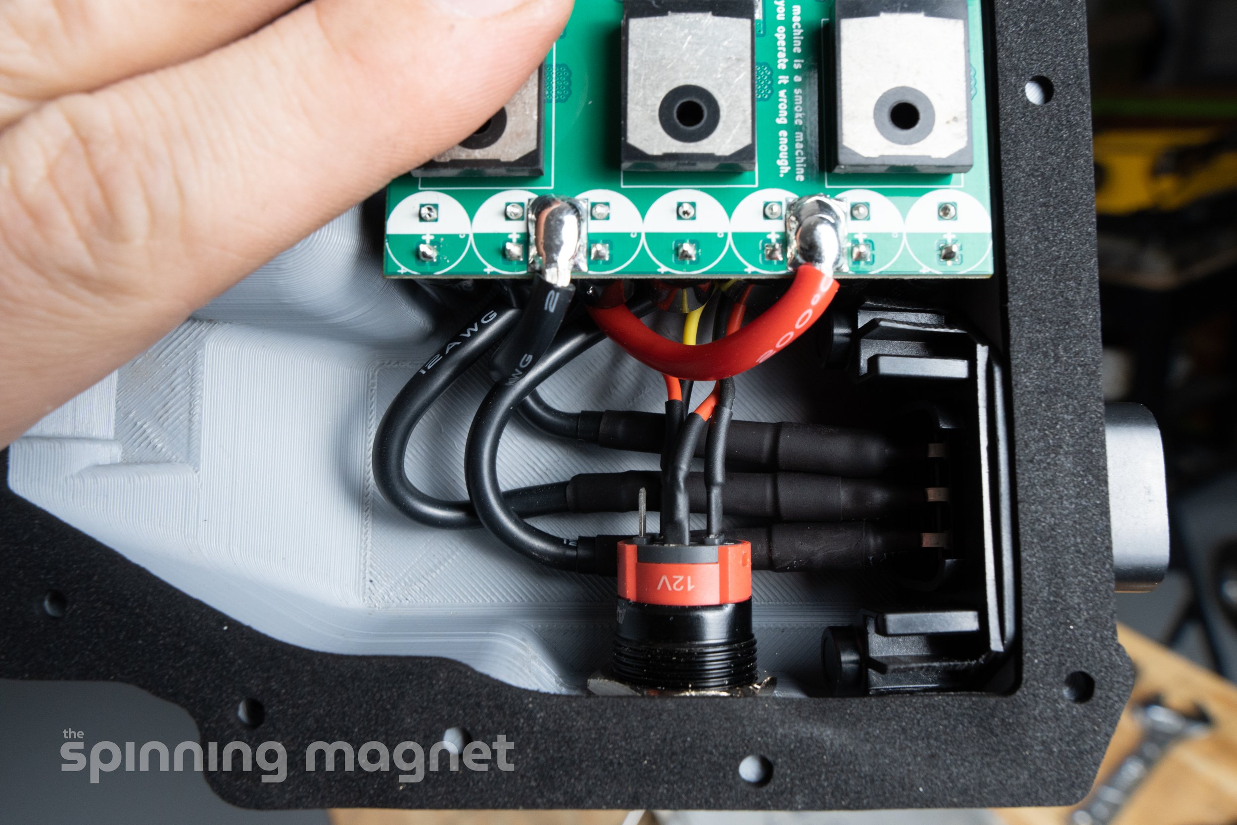
8. Solder the blue and purple wires.


I didn’t have any blue or purple wire on hand unfortunately, so I used red for both connections. I understand that this may be confusing, so I modified the colors in post in order to clear things up. In subsequent photos, you may notice that the wires that I used are actually red.
a. The blue wire connects from the “NO” post on the power button to the lower left post on the back of the 16 pin Molex connector.
b. The purple wire connects from the lower solder cup on the XLR port to the upper left post on the back of the 16 pin Molex connector.
c. Cut each wire to size. You don’t want there to be any strain on the wire, but you want to trim the excess to make cable management easier.
d. For each solder joint, twist the wire around the post and then apply some flux. Heat and solder into place.
e. Cover each connection with some heat shrink.
Note: Soldering the wires directly to the Molex connector will make future disassembly difficult, since the wires will need to be desoldered. This could be remedied by installing a connector in each wire (such as bullet connectors). Looking back, I should’ve included this in the guide and I may add it in the future.
9. Check polarity.


If you haven’t already disassembled your XR, go ahead and do that now. You will need the battery module removed for testing. Be sure that the battery is at least 50% charged before continuing.
a. Connect the stock wiring harness to the 16 pin Molex connector.
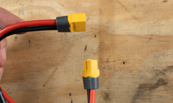
b. Use your multimeter to check the voltage at the XT60 connector. If the polarity is correct, you should receive a positive voltage reading when touching red to red and black to black.
c. If you find that polarity is in fact reversed, pause here for now and order this Reverse Polarity Adapter from MakersPEV. You can also make your own with some XT60 connectors and 12 AWG wire.
Do not connect your Little FOCer to the XT60 until correct polarity is confirmed. If the polarity is reversed - which may be the case due to Future Motion booby trapping - then you will fry your VESC.
d. After polarity is confirmed, disconnect the wiring harness from the 16 pin Molex connector.
10. Test the Little FOCer.


a. Verify that your wiring harness was disconnected in the previous step.
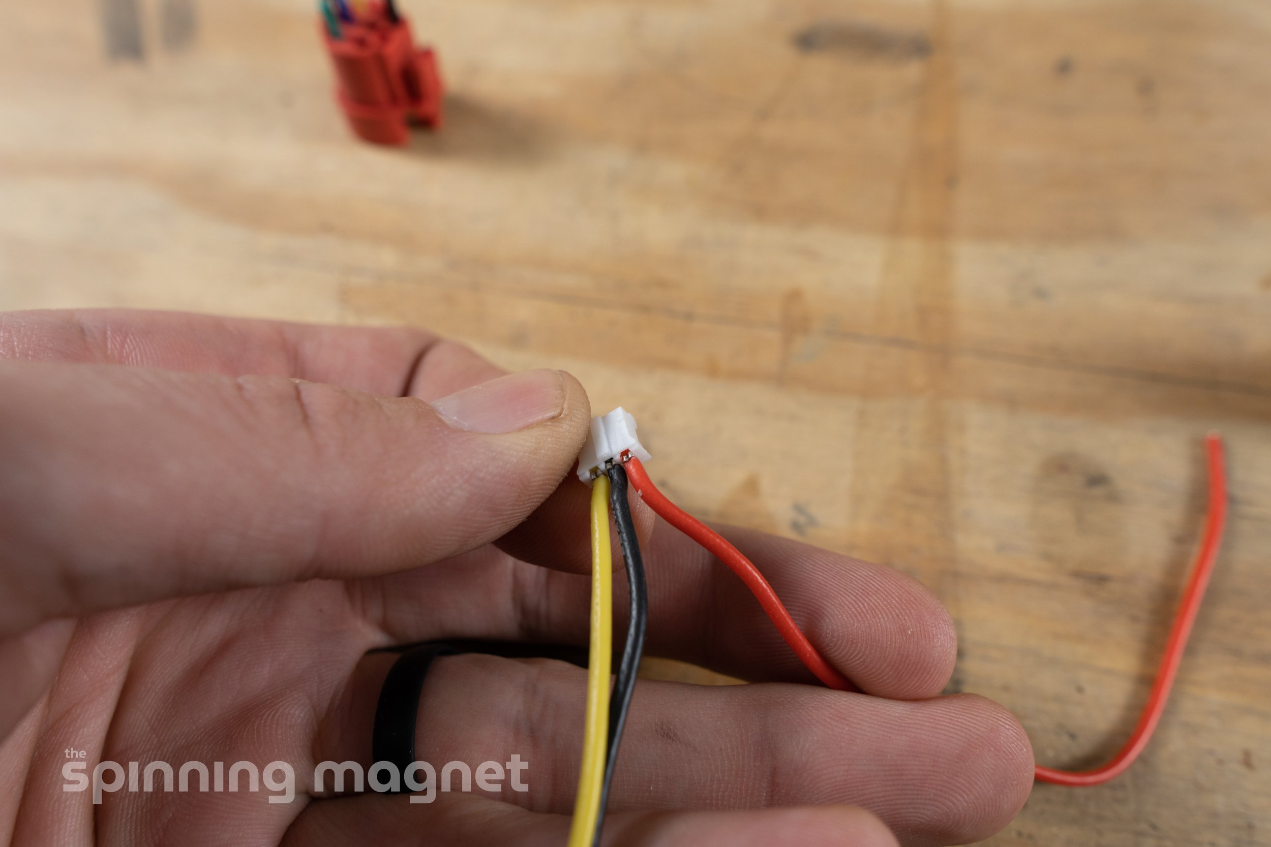
b. Connect the 3 pin JST from the power button to the connector pictured above on the Little FOCer.
c. Connect the male and female 3 pin white Molex connectors for the XLR charging port.
d. Connect the XT60 from the 16 pin Molex to the XT60 on the Little FOCer.
e. Make sure the Little FOCer is moved away from anything metal.
f. Connect the wiring harness to the 16 pin Molex.
g. Be careful with anything metal around the Little FOCer or the charging port from this point. It is now potentially a live circuit.
h. Press the power button. It should illuminate. If not, disconnect everything, starting with the wiring harness and then recheck your wiring.
i. Once the power button is illuminated, check to make sure you can see the Little FOCer in the VESC Tool mobile app. For instructions on downloading and connecting with the mobile app, skip ahead to the software section installing and connecting with VESC Tool and then come back here.
j. Once you’ve verified connectivity, press the power button again to turn the VESC off.
k. Connect your charger to the XLR port. Again, the power button light should illuminate. The light on the XR charger should also turn red.
l. Verify that you can connect to the Little FOCer using the VESC Tool mobile app.
m. Disconnect your charger from the XLR port.
n. Disconnect the wiring harness from the 16 pin Molex.
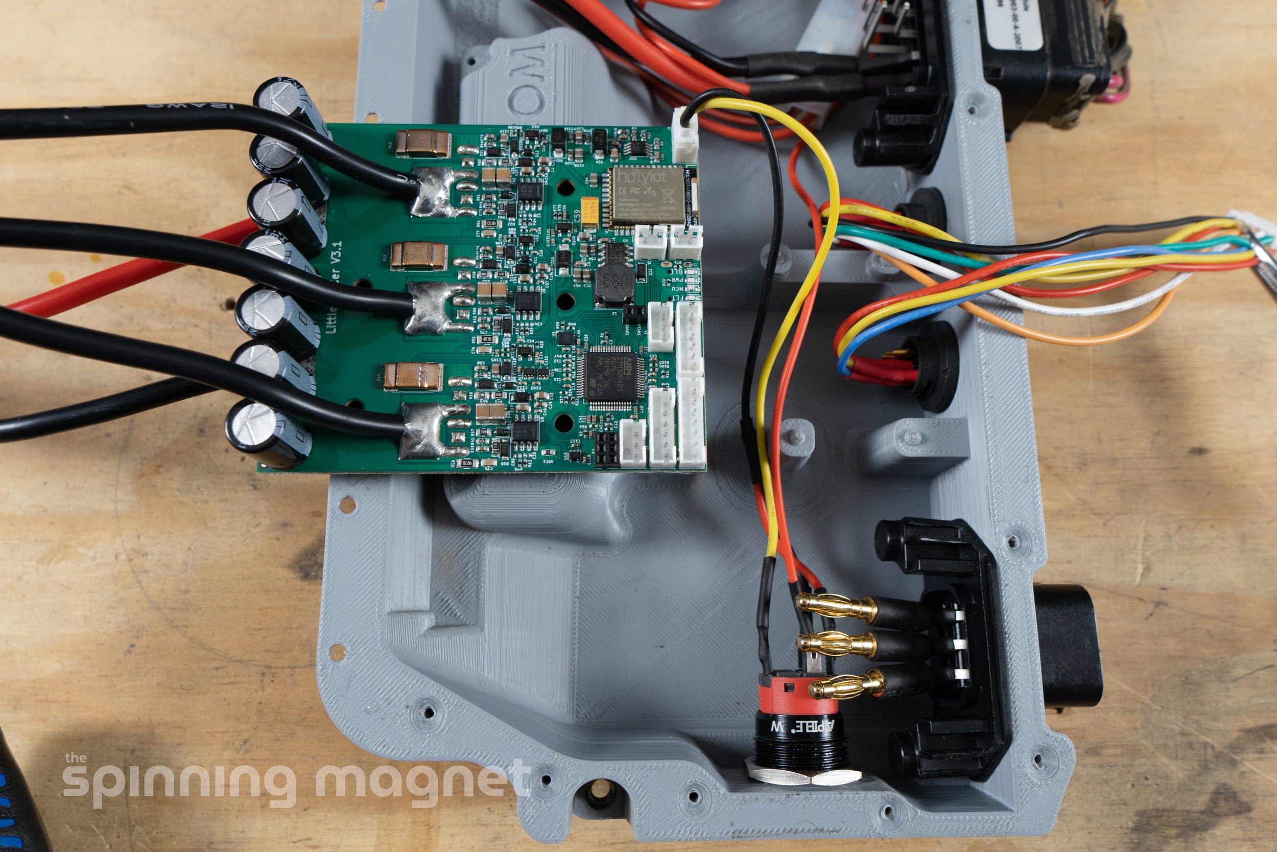
11. Get everything connected and the wires routed.


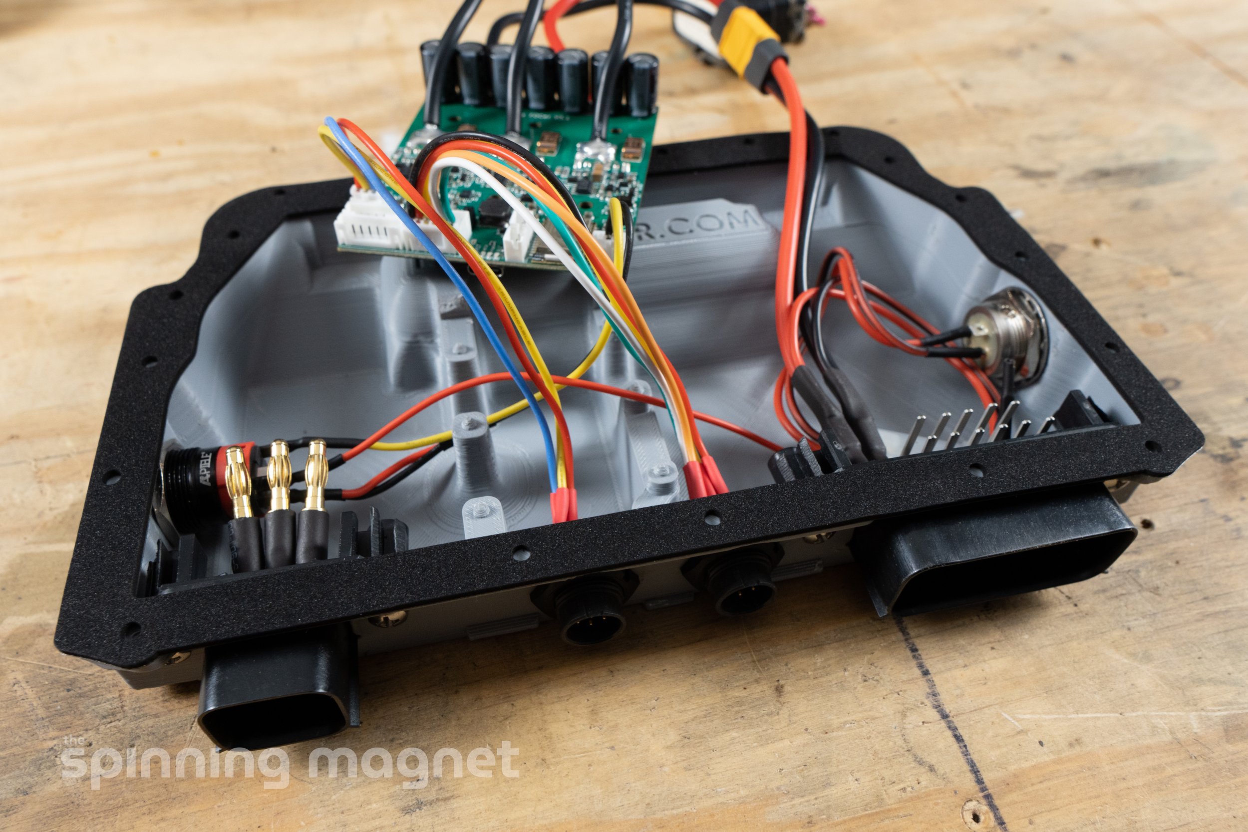


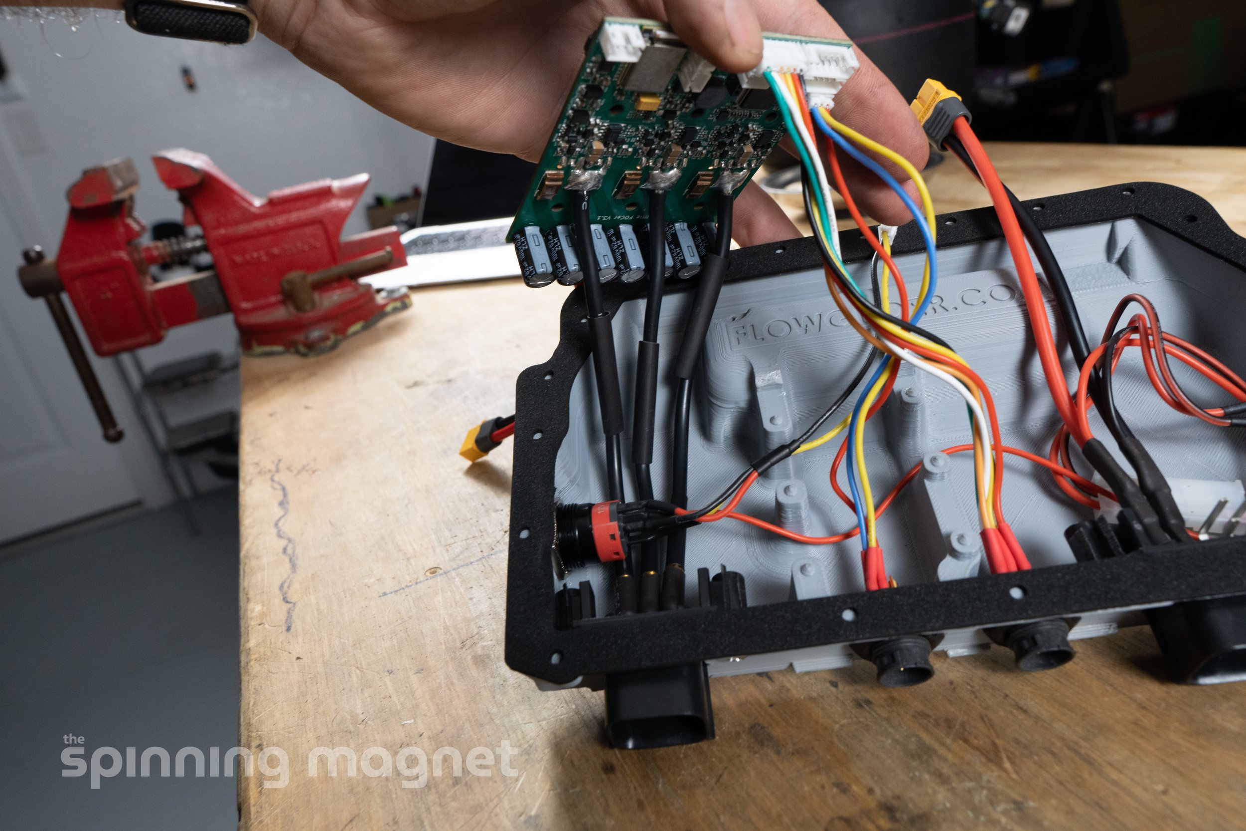


This step will require some patience and tenacity. There isn’t much room for all of the wiring, so you need to be careful to make sure nothing is pinched and there isn’t any strain on any of the wires. Go slowly and reference the cable routing diagram and the photos. I tried to get plenty of photos of this process, but it takes a little trial and error.
a. At this point, you should already have the 3 pin white Molex connected for the charging port. If not, connect it.
b. You should also already have the 3 pin JST connected from the power button the Little FOCer. If not, connect it.
c. Connect the 3 pin JST from the footpad connector to the Little FOCer.
d. Connect the 6 pin JST from the hall sensor connector to the Little FOCer.
e. Connect the XT60 from the 16 pin Molex to the Little FOCer.
f. Connect the three bullet connectors from the Little FOCer to the motor power 6 pin Molex. It does not matter which connectors go to which. Install heat shrink around the connectors. You may need to loosen the power button retainer nut and shuffle things around to get space to work the bullet connectors together.
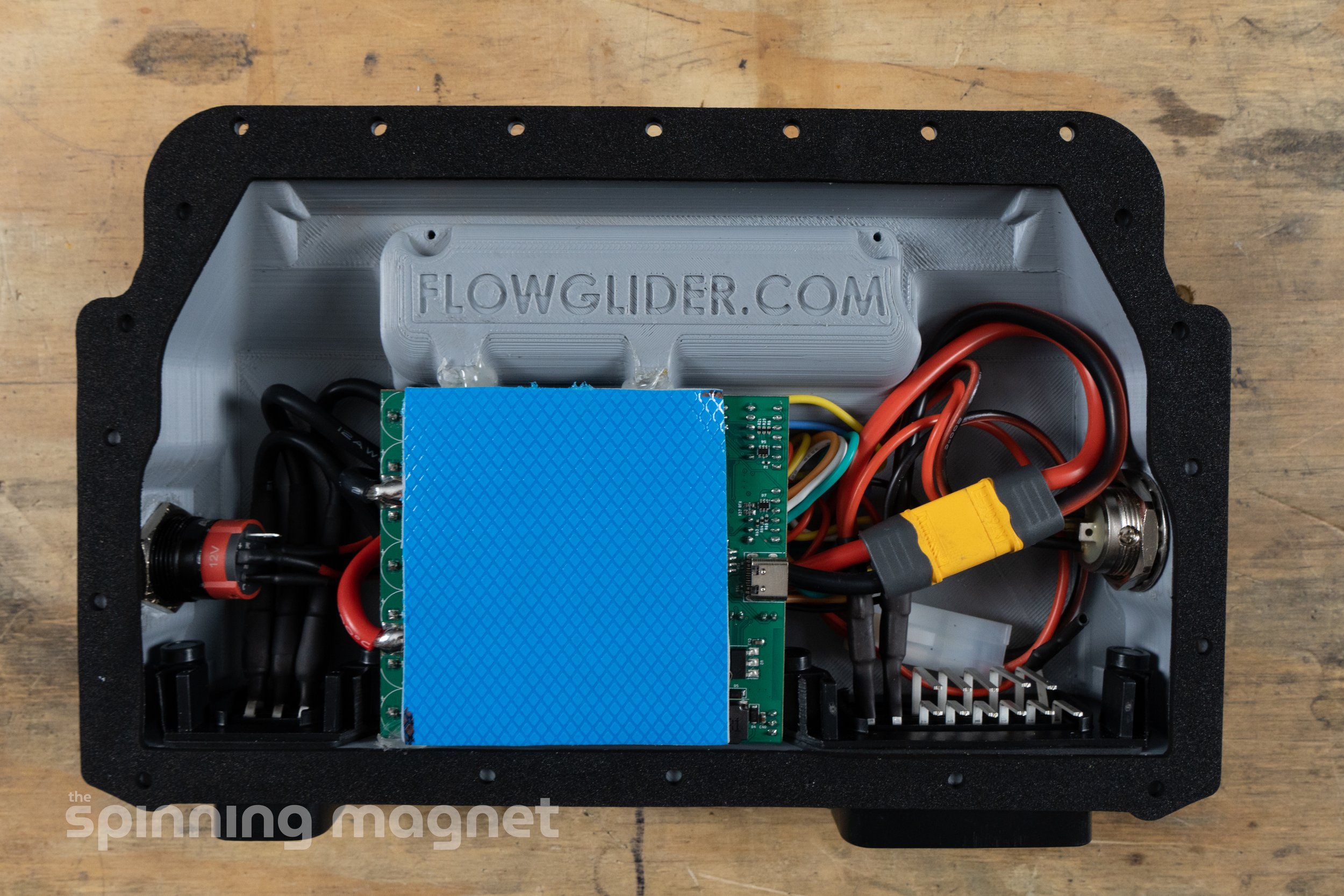
g. Once everything is connected and routed properly, the six holes in the Little FOCer will line up with the six posts in the Flowglider box. When you push the Little FOCer into place, there will be a little bit of resistance or springiness because of all the wires, but it should not have to be forced into place. Once it fits correctly, the top of the Little FOCer should sit flush with the top of the Flowglider box.

Using Hot Glue
TIP: Put a couple of drops of hot glue on the edge of the Little FOCer where it meets the Flowglider box, near the connectors. This will help keep it in place during the next steps.
12. Install the lid gasket.

a. If you have adhesive backed fishpaper, you can use a piece on the lid to prevent a short of the 16 pin Molex. You could also place some electrical on top of the vertical posts. Most likely, neither of these are necessary though.
b. Remove the paper backing, line up the black neoprene gasket, and stick it on the lid.
13. Install the thermal pad and the lid.


a. (Optional) Cut the thermal pad to size before installing. It should just cover the MOSFETs on top of the Little FOCer. This will leave you with some spare material if you need it. The size should be about 2 1/4” x 2 7/8”.
b. Clean the MOSFETs with rubbing alcohol.
c. Remove the slick non-textured backing from the thermal pad and place it over the Little FOCer.
d. Then remove the textured backing.
e. Carefully line up the hole from the lid to the Flowglider box.
f. Install all of the pointed wood screws on the top side of the lid. Do not overtighten, as you will strip out the plastic of the Flowglider box.
g. Install all of the non-pointed machine screws from the bottom of the Flowglider box, going up into the lid and into the riv-nuts. Use a drop of threadlocker on these screws so that they stay in place.
14. Install heat set brass inserts.


The Plastic Spider lid kit should have come with four heat set inserts. These will need to be installed with your soldering iron. Reference this article from CNC Kitchen if you’ve never installed heat set inserts: TIPS & TRICKS FOR HEAT-SET INSERTS USED IN 3D PRINTING
a. The long inserts will go in the two holes near the front of the Flowglider box.
b. The shorter inserts will go in the other two holes near the back of the box.
c. Use a #10 heat insert tip on your soldering iron.
d. Set the temperature of your soldering iron to 10-20 degrees higher than the melting point of the material of the Flowglider box. For my box with PA6-CF, I used ~320 degrees Celcius. For PLA, you’ll want to keep it around 275.
15. Reassemble your onewheel.


With the inserts installed, the controller module is done! Go ahead reinstall/reconnect everything just like you would with a Future Motion XR. It will power on at this point, but it won’t be rideable until we configure the software.
References
Software Setup
Download and Install VESC Tool
VESC Tool is the open-source application that you will use to configure your VESC onewheel. The interface is a lot easier to navigate on a larger device, therefore I recommend performing the initial configuration from a desktop or laptop. But, it can be done from mobile as well. VESC Tool is available on pretty much every platform, so follow the instructions below depending on your device.
While working on the software setup and configuration, your VESC will need to remain powered on. The Future Motion BMS has a feature that will power off the device after being idle for 20 minutes, so you may need to turn the board back on and reconnect periodically.
Jump to your device:
iPhone / iPad
VESC Tool is available from the App Store for $3.99, so simply follow the link below:
Android
VESC Tool is available from Google Play for $3.99, which is the easiest way to get the app. Here is the link:
Alternatively, you can sideload the APK from vesc-project.com, but that won’t be covered in this guide.
Windows / Mac / Linux
For the desktop versions (Windows, Mac, and Linux), installation is slightly more involved. You’ll need to create an account at vesc-project.com, “purchase” the application (for zero dollars), then download and install it. If you need help, see the screen shots and the instructions below.
1. Navigate to https://vesc-project.com.
2. Do the simple math problem for CAPTCHA and then click on “Create new account” in the top right.

3. Enter a username, email address, the word VESC, and solve another CAPTCHA. Click on the “Create new account” button.

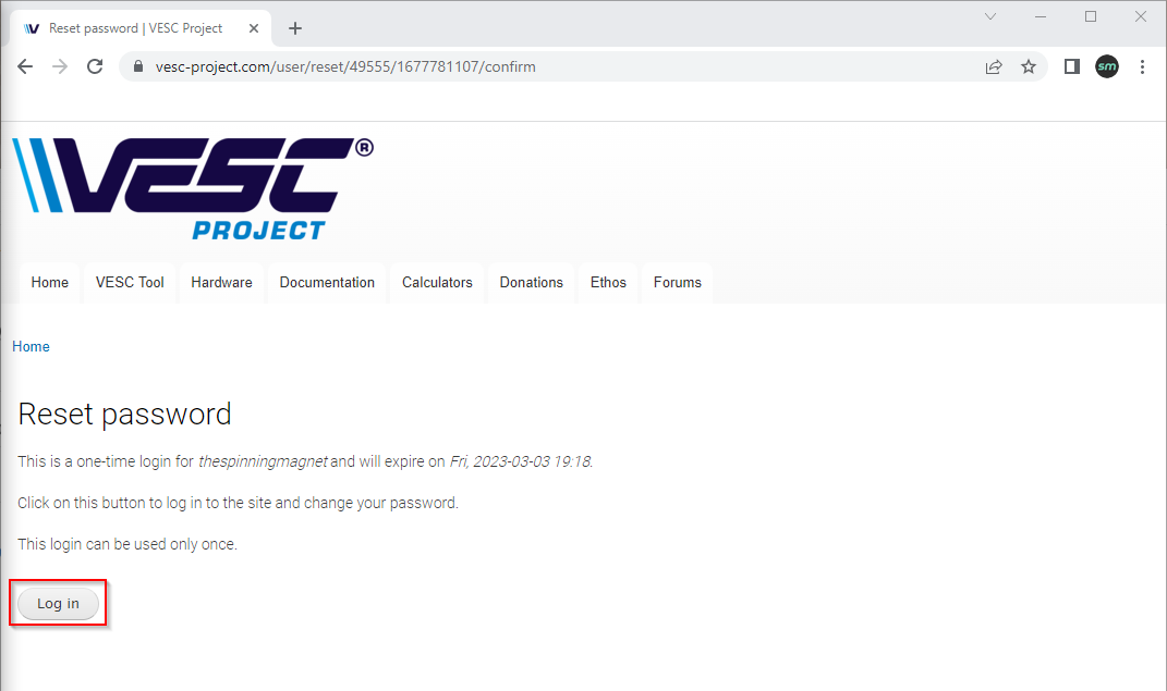
4. You should receive an email from vesc@vedder.se with a link to set your password. Follow the link in the email.

5. Set a password by clicking the “Log in” button.
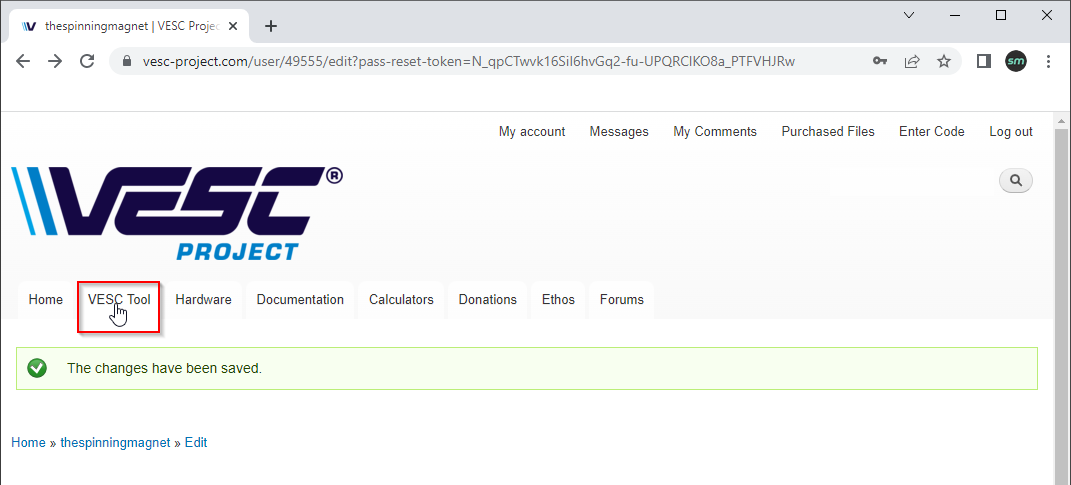
6. Enter a new password then scroll down and click the “Save” button.


7. Click on “VESC Tool” from the navigation bar.
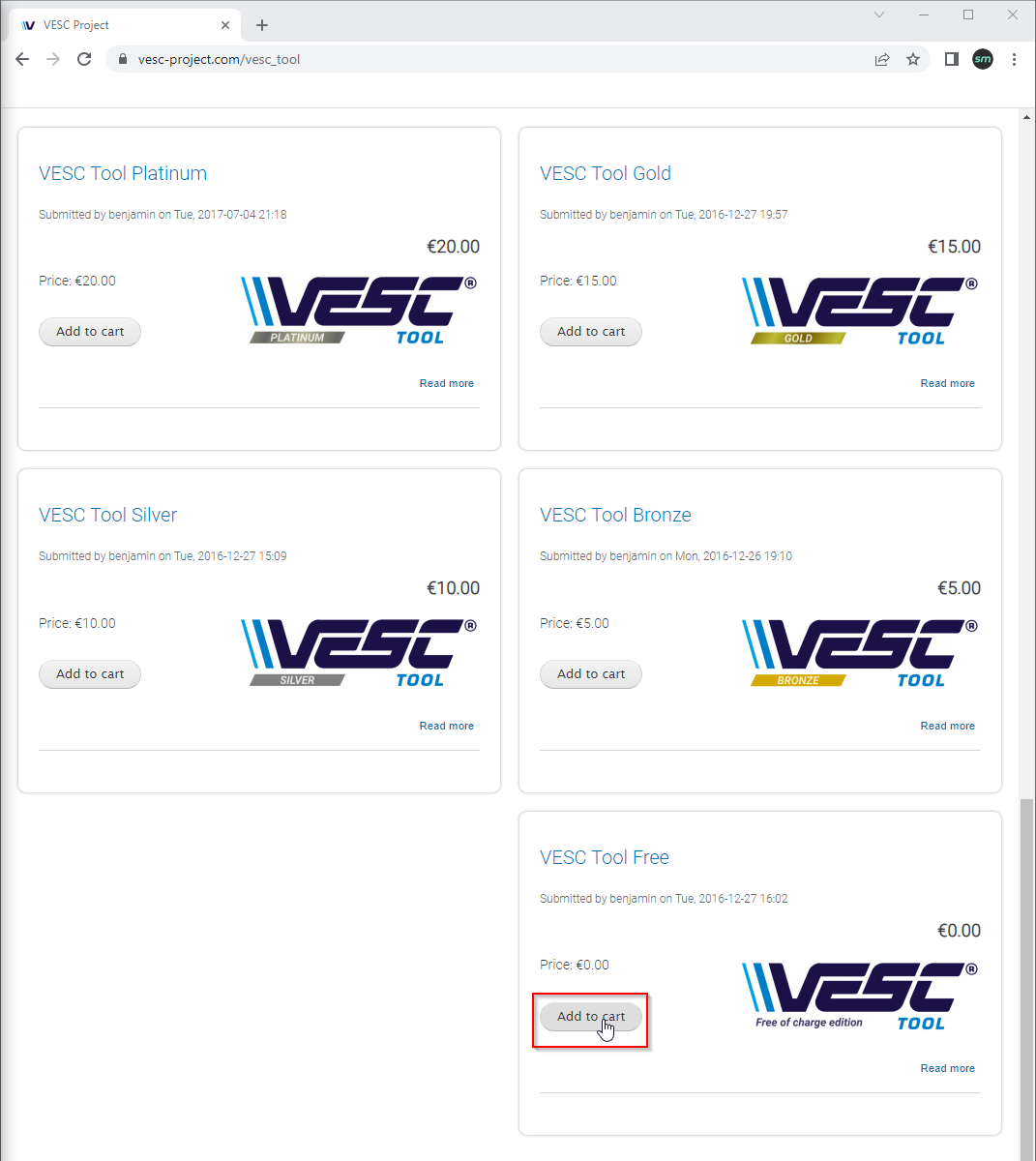
8. Scroll down and select which VESC Tool version you want. From the free version to platinum, they are all the same. The only difference is the donation amount. Click the “Add to cart” button.
9. Click the “Checkout” button.

10. Scroll down to enter your billing information. If you selected the free version, you only need to give a name, address, and phone number; no payment method. Once you’ve entered your info, click the “Review Order” button.

11. If everything looks good, click the “Submit order” button.

12. Click on “Purchased Files” from the top navigation bar.

13. Download the zip file for your operating system.

14. Install VESC Tool like you would install any other application on your operating system.
Connect to Your VESC from Mobile
First, we’ll be connecting to the Little FOCer using Bluetooth on your mobile device. Later, I’ll explain how to connect from your desktop, using your mobile device as wireless bridge.
You can also use a MacBook to connect directly to the Little FOCer via Bluetooth, but it can be little buggy (see the conversation on pev.dev). The other option is to connect with USB, but this should only be necessary if Bluetooth isn’t working.
All of my screenshots were taken from an iPhone, but the Android version should be nearly identical.
1. Before we begin, make sure your board is powered on.
2. When you open VESC Tool for the first time on your mobile device, you will need to grant it permission to use Bluetooth.

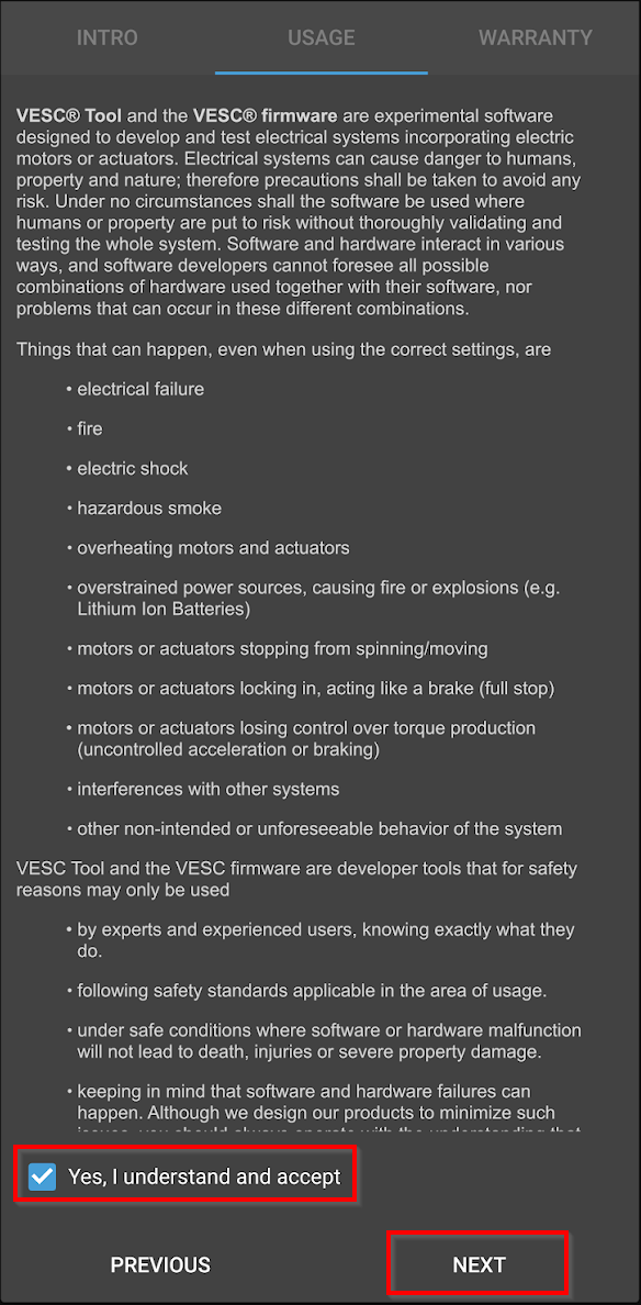
3. Go through the Intro, Usage, and Warranty information by tapping “NEXT” and then “FINISH”.


4. VESC Tool will scan for VESC devices in the area. If it doesn’t find any, you will see “- -SCANNING- -” and a blue spinning circle. If it never finds any devices, make sure your board is powered on. Once it is powered on, tap “SCAN” and select “Scan BLE” to check for devices again.

5. Once a device is found*, it will be listed as “Little FOCer XXXXX BUILTIN”. Tap “CONNECT” to connect to your VESC.

* Unless you have another VESC, you’ll only see one device listed here.
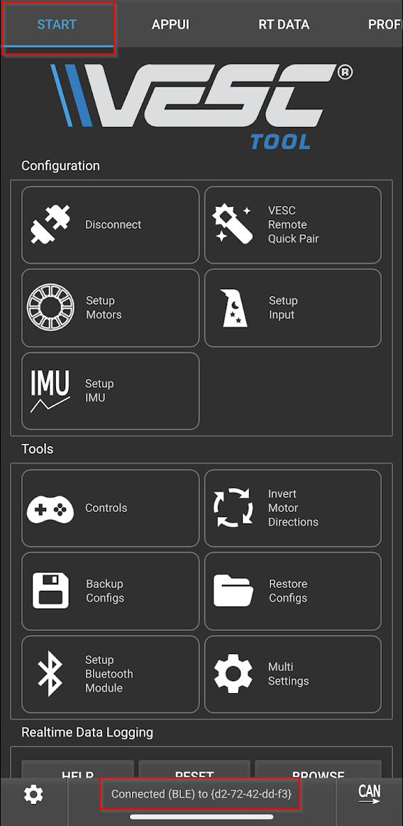
6. Once you’re connected, you’ll see the “Start” tab and the “Connected (BLE) to {xx-xx-xx-xx-xx}” status message at the bottom of the screen.
If you’re still working on getting your hardware installed, click here to return back to the hardware setup section.
Connect to Your VESC from Desktop
We’ll now connect your desktop or laptop to your VESC using the Wireless Bridge option on the VESC Tool mobile app. From now on, I will only use the term desktop when referring to either your desktop or laptop computer. Your mobile device and desktop will need to be on the same network (wireless or wired LAN) for this to work.
1. Verify that your board is powered on and your mobile device has the “Connected (BLE)” status message at the bottom of the screen.
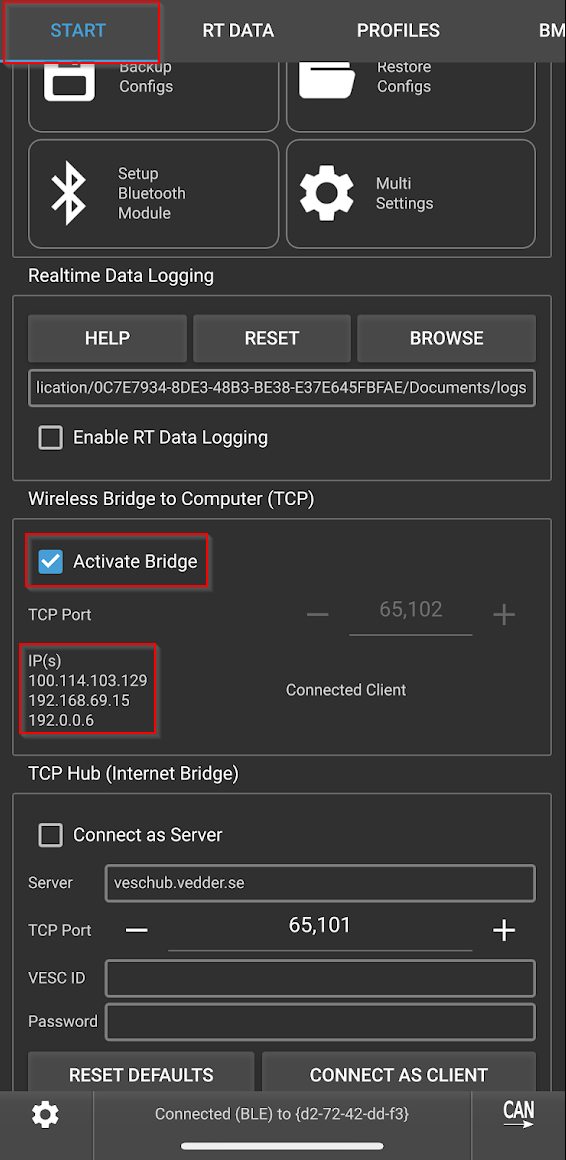
2. After connecting to your VESC with your mobile device, scroll to the section labeled “Wireless Bridge to Computer (TCP)”. Check the box for “Activate Bridge”. Take note of the IP addresses.
3. Launch VESC Tool from your desktop.
On Windows, you simply double-click the “vesc_tool_6.00.exe” file that you downloaded in the VESC Tool installation section.
On Mac, VESC Tool will appear in your Applications folder after installation.
On Linux, you will need to figure that shit out because you’re a Linux user and you got this 👍
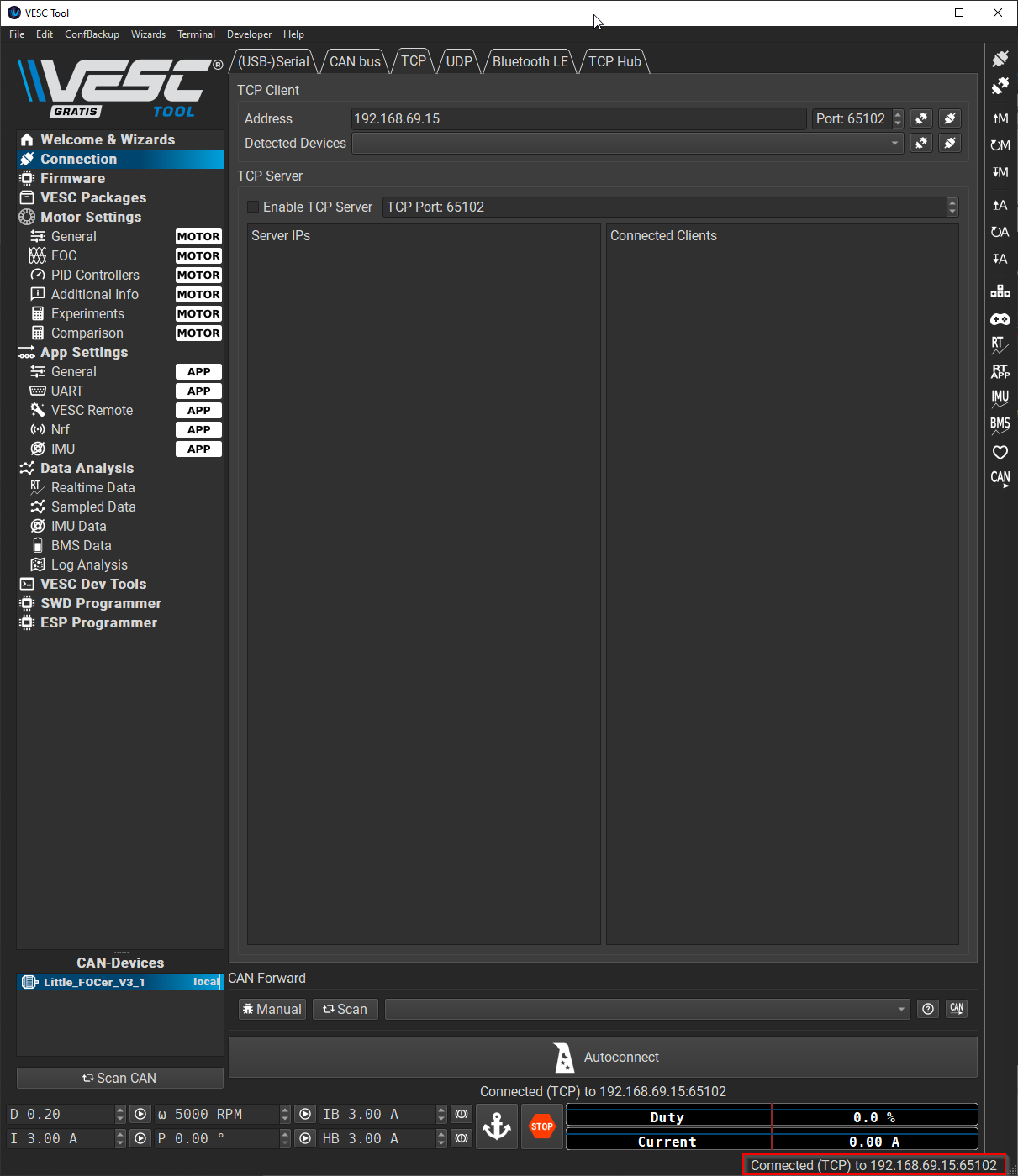
4. In the desktop VESC Tool application, from the left menu bar navigate to Connection > TCP. In the “Address” field, input the IP address of your mobile device. Click the small connect button.
Note: The mobile app will list multiple IP addresses. Your phone’s actual IP address most likely begins with 192.168 if your home network is using default settings. If you don’t see an IP starting with 192.168, just try connecting with each IP address listed and take note of which one works.
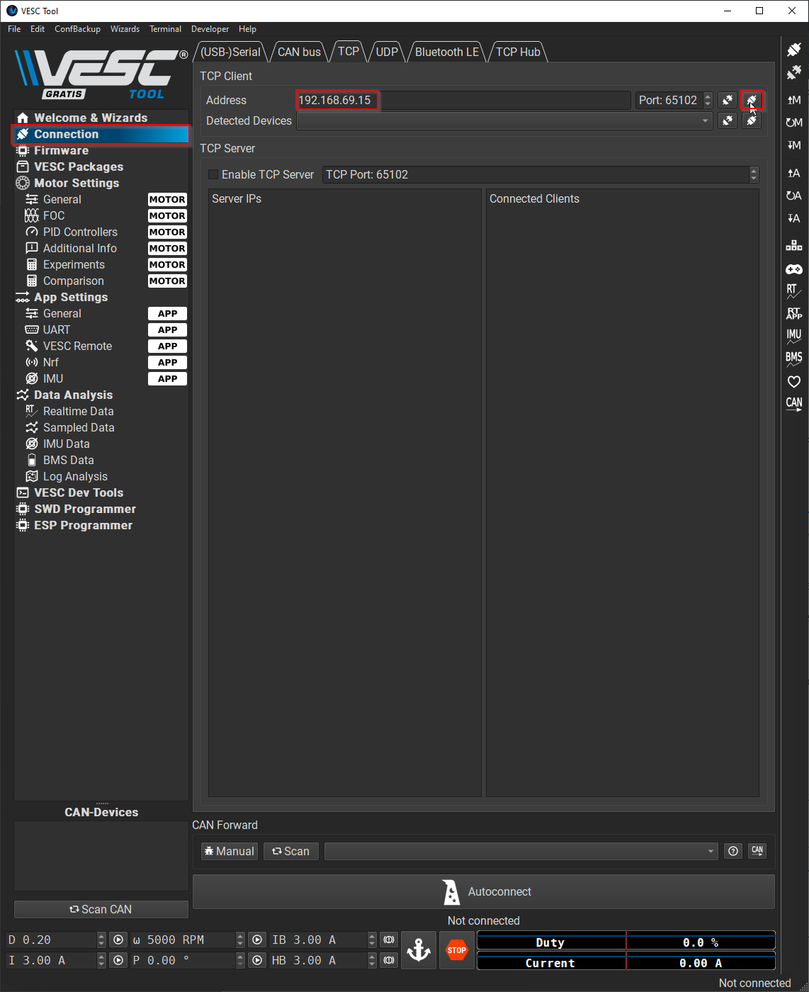
5. Once you are connected, you’ll see the status at the bottom of the desktop interface change from “Not connected” to “Connected (TCP) to x.x.x.x:65102”
Update the Firmware
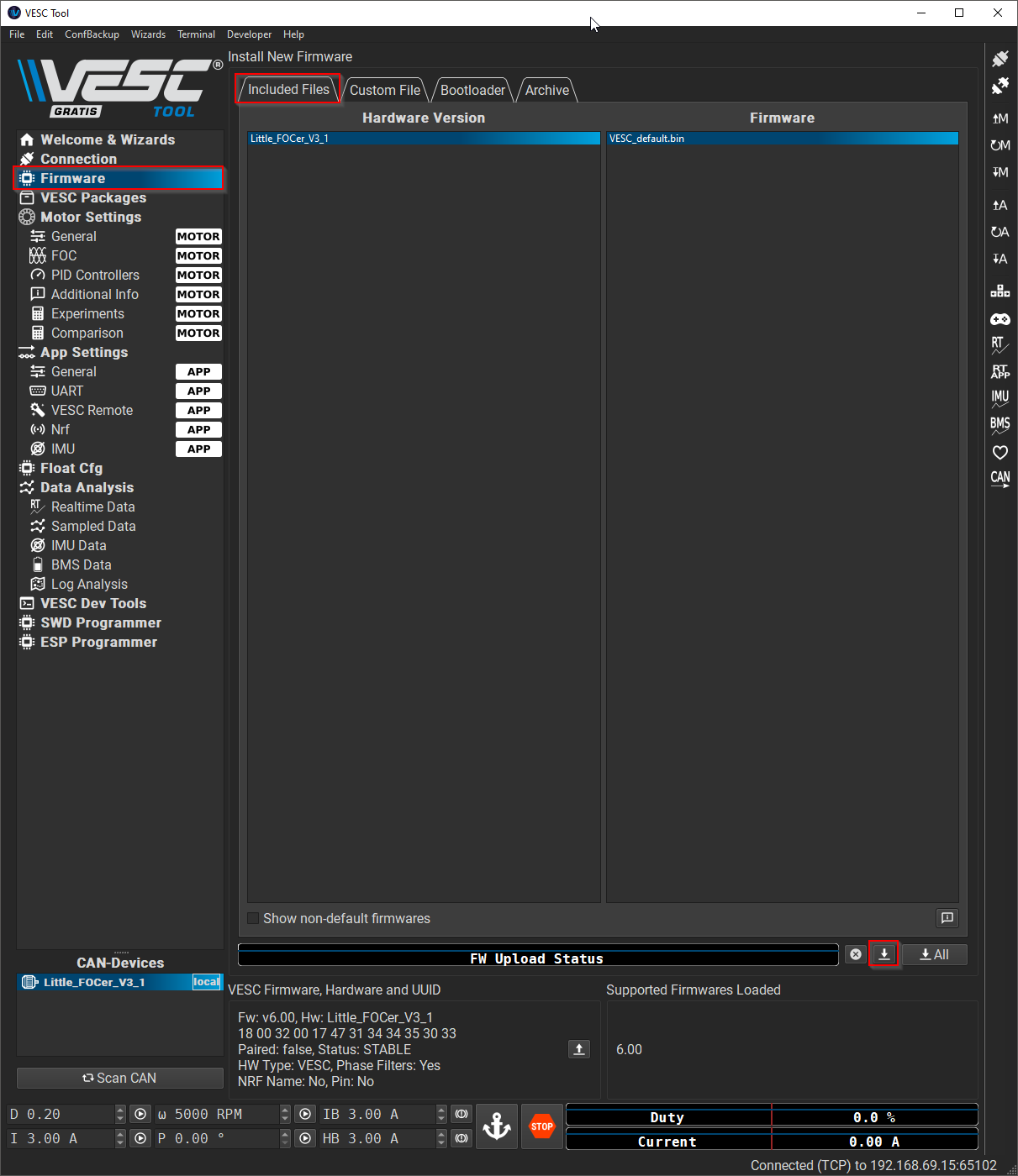
1. Verify that your board is powered on and you see the “Connected (TCP)” status message at the bottom of the desktop VESC Tool app.
2. From the left menu bar, Navigate to Firmware > Included Files. Click on the down arrow button to update the firmware on your Little FOCer. At the time of publication of this guide, the most recent firmware version was 6.00. Yours may differ.
Note: this procedure will update your firmware and reset your settings to default. Proceed with the firmware update even if you are on the most recent version.
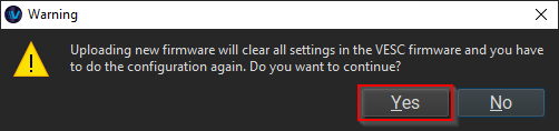
3. Click “Yes”.
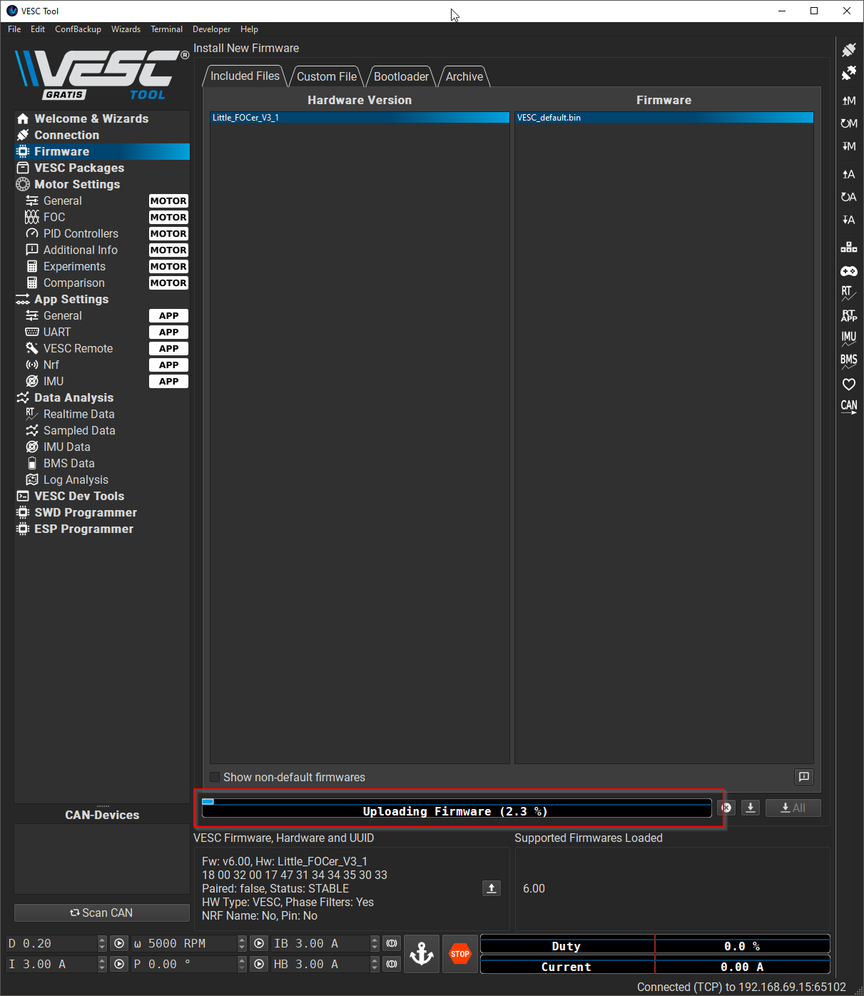
4. You will see multiple messages along the status bar during the firmware update. It will take 1-5 minutes to complete.
5. Once it’s done, wait at least 15-20 seconds.
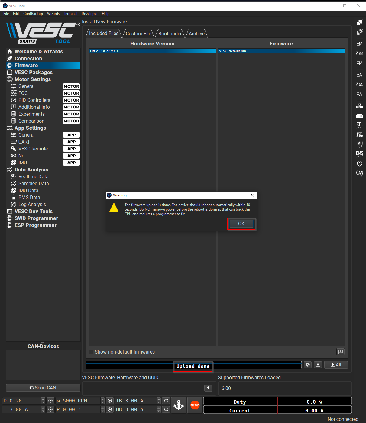
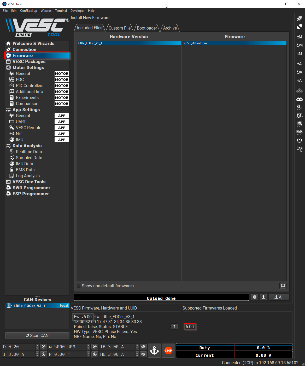
6. Reconnect your mobile device and your desktop.
7. From the left menu bar, navigate to Firmware. In the bottom section, confirm that the current firmware (on the left) matches the loaded firmware (on the right).
Calibrate the Motor
This section is almost entirely based on Soulrider’s excellent motor configuration cheat sheet on pev.dev. Which was based off of surfdado’s videos.
1. Support your onewheel from either side on a level and stable surface so that the tire is not touching anything. I recommend using a couple of chairs, sturdy boxes, or milk crates. The motor is going to spin during the calibration process and it needs to be off of the ground.
2. Make sure your board is powered on and connected to the desktop VESC Tool.
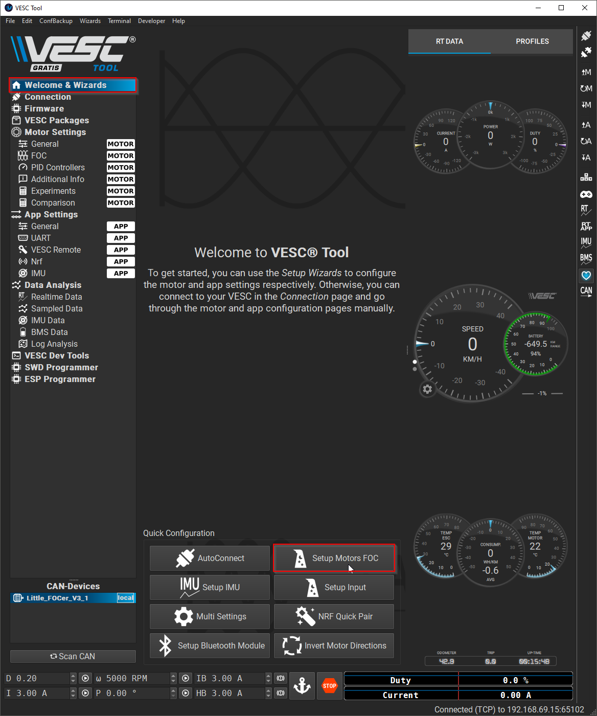
3. From the left menu bar on the desktop app, navigate to Welcome & Wizards > Setup Motors FOC.
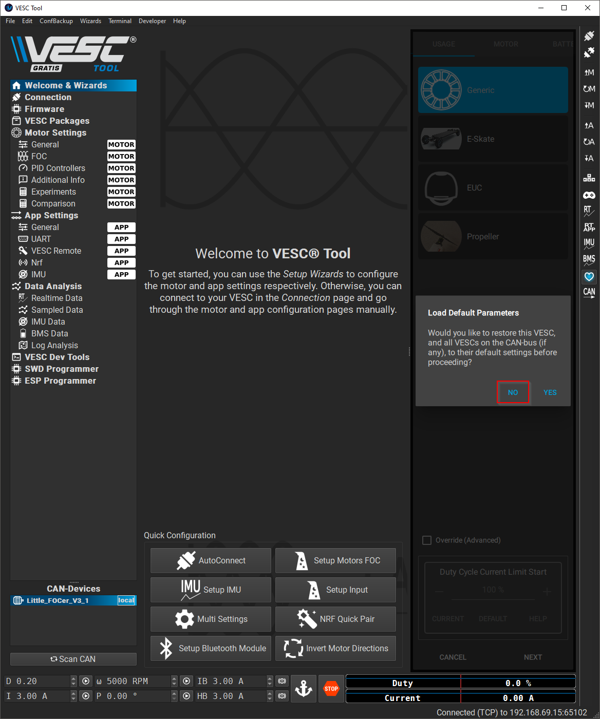
4. Click "No”. Do not load default parameters.
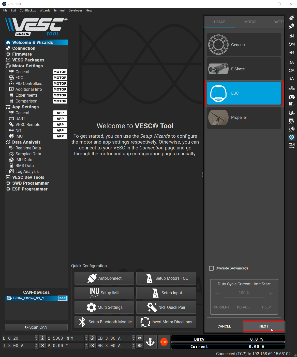
5. Select “EUC” then click “NEXT”.
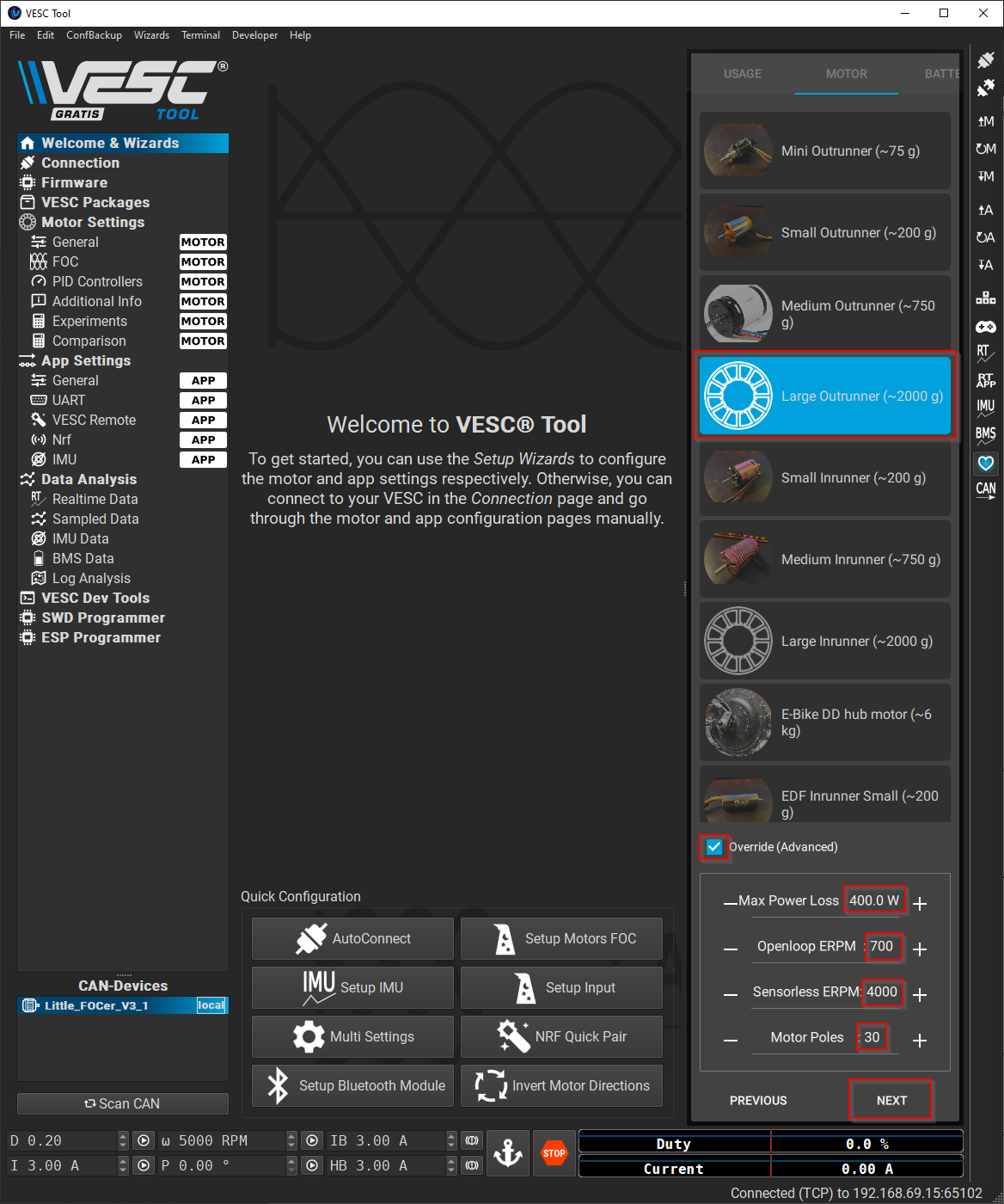
6. Select “Large Outrunner (~2000 g)” and check the box next to “Override (Advanced)”. Enter the following parameters:
Max Power Loss: 400 W
Openloop ERPM: 700
Sensorless ERPM: 2000
Motor Poles: 30
Click “Next”
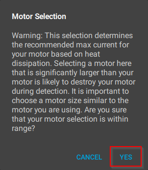
7. Make sure you have “Large Outrunner (~2000 g)”. If you do, click “Yes”.
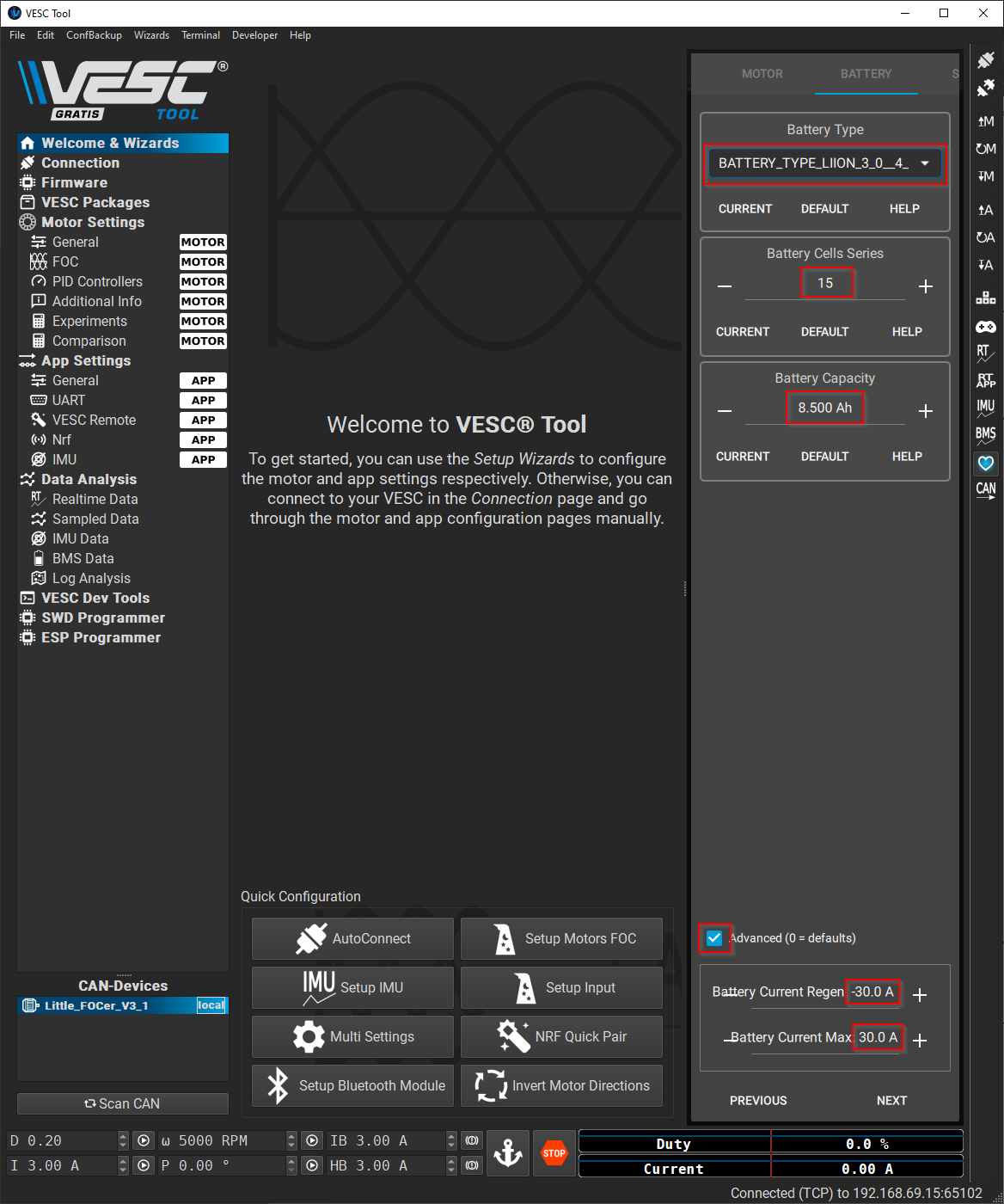
8. Enter the following parameters:
Battery Type: BATTERY_TYPE_LIION_3_0_4_2
Battery Cells Series: 15
Battery Capacity: 8.5
Check the box next to “Advanced” and enter the follow parameters:
Battery Current Regen: -30.0 A
Battery Current Max: 30.0 A
Click “Next”.
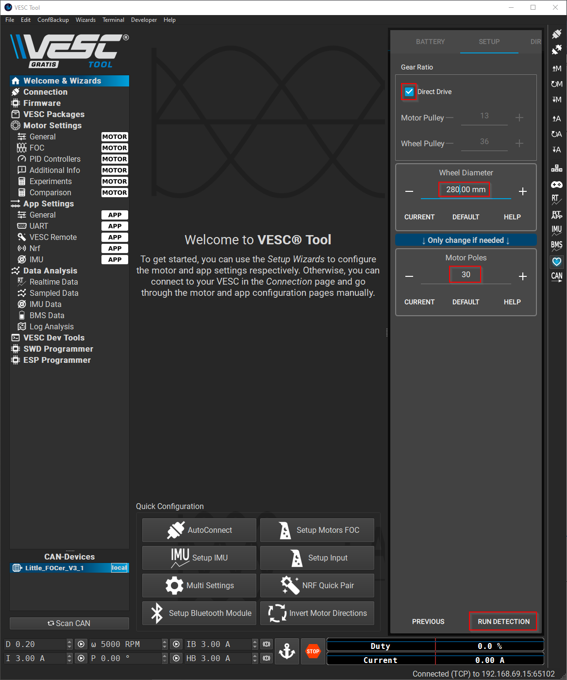
9. Check the box next to “Direct Drive”. Enter the following parameters:
Wheel diameter: 280 mm
Motor Poles: 30
Click “Run Detection”.
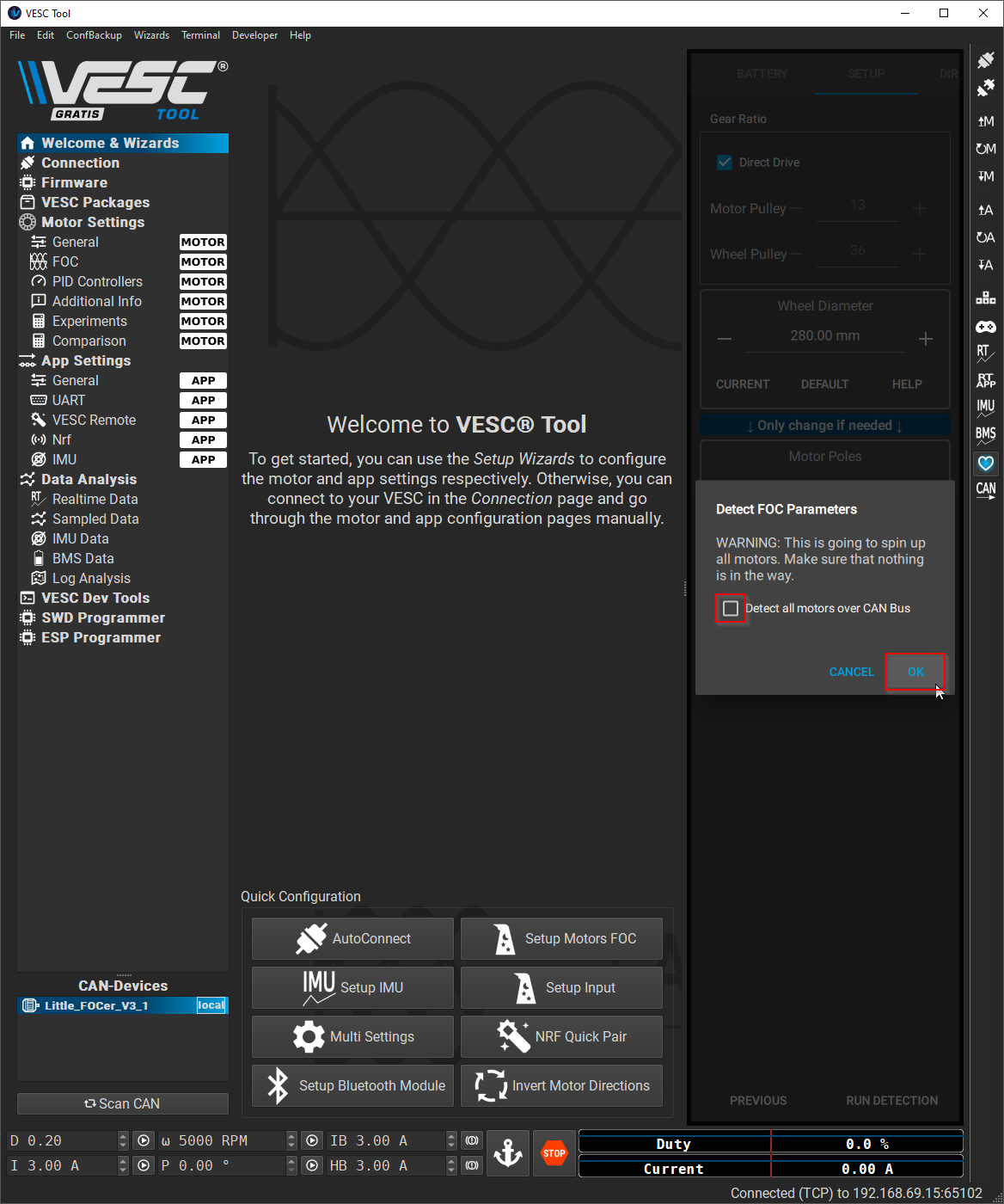
10. Uncheck the box next to “Detect all motors over CAN Bus” and click “OK”.
The motor will now spin
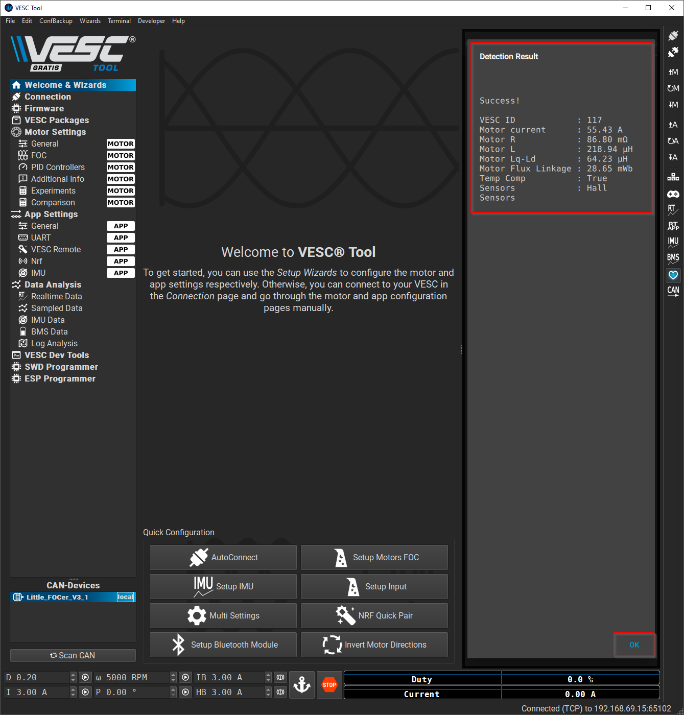
11. If the motor calibration was successful, you’ll see the following screen with similar values. Click “OK”.
Note: If your values are wildly different, you can try re-running the motor calibration.
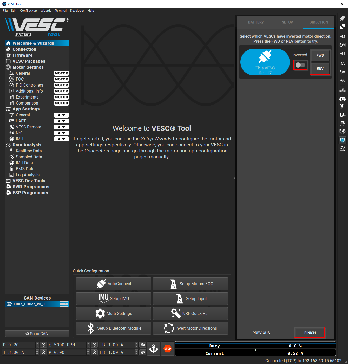
12. Test the motor direction by clicking “FWD” and “REV”. When spinning forward, the top of the tire should move towards the front of the board and vice versa. If the motor is not moving in the correct direction, change the “Inverted” toggle. Test it again to make sure the motor is moving in the right direction. Click “Finish” once the motor is spinning in the right direction.
13. Press the “Write Motor Config” button on the right side to save the motor configuration to memory. This shouldn’t be necessary, as the calibration process will write the config, but better safe than sorry.
Motor Configuration
After running the motor calibration, we need to manually set a few more things. A lot of these parameters are specific to a stock XR style battery (stock, CBXR, JWXR, etc). If you’re referencing this guide, but using a different battery, be wary.
Motor Settings > General
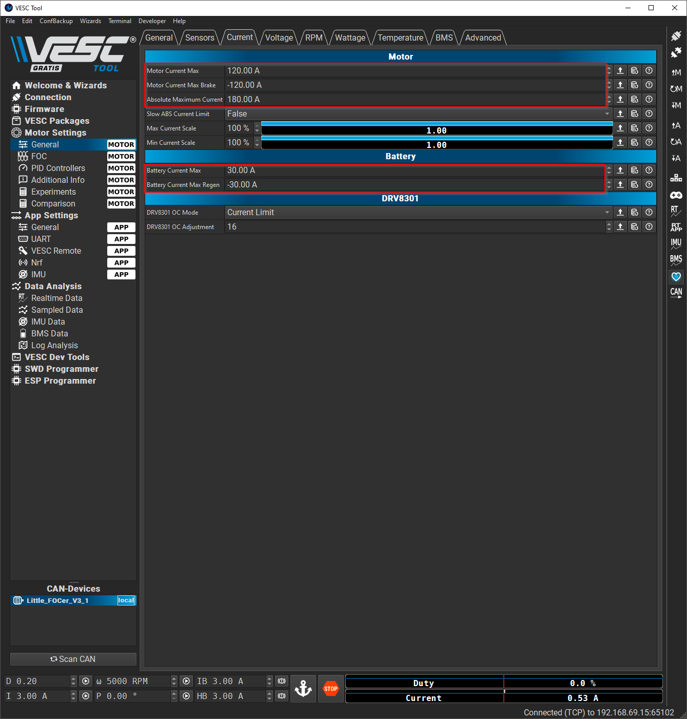

1. From the left menu bar, navigate to Motor Settings > General > Current tab. Enter the following parameters:
Motor Current Max: 120.00 A
Motor Current Max Brake: -120.00 A
Absolute Maximum Current: 180.00 A
Battery Current Max: 30.00 A
Battery Current Max Regen: -30.00 A
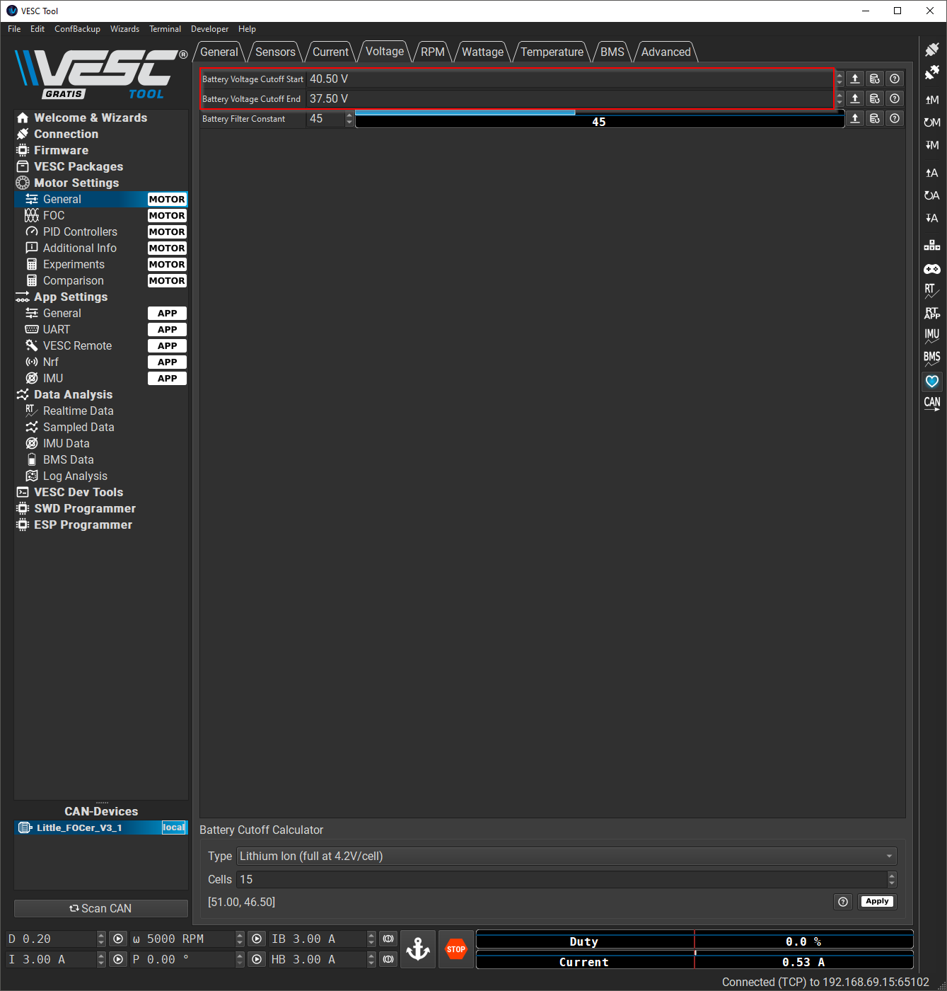
2. Navigate to Motor Settings > General > Voltage tab. Enter the following parameters:
Battery Voltage Cutoff Start: 40.5 V
Battery Voltage Cutoff End: 37.5 V
3. Navigate to Motor Settings > General > Temperature tab. Enter the following parameters:
Motor Temperature Sensor Type: NTC 10K at 25°C
Acceleration Temperature Decrease: 0%
MOSFET Temp Cutoff Start: 75°C
MOSFET Temp Cutoff End: 80°C
Motor Temp Cutoff Start: 80°C
Motor Temp Cutoff End: 90°C
4. Press the “Write Motor Config” button on the right hand side and verify that you see the “MCCONF Write OK” status message.

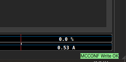
TIP: Eventually, you might try to write a config once the board has turned off or the connection has timed out. If this happens, reconnect to the board and press the “Write Motor Config” or “Write App Config” button again. Scroll through the changes you just made to make sure they took.
Motor Settings > FOC


1. Navigate to Motor Settings > FOC > General tab. Enter the following parameters:
Observer gain: 1/2 of the current value. Should be somewhere between 0.6 and 0.7.
For example: mine was set to 1.22, so I changed it to 0.61.
2. Navigate to Motor Settings > FOC > Hall Sensors tab: Enter the following parameters:
Sensorless ERPM: 2000.00
Hall Interpolation ERPM: 200.00
3. Navigate to Motor Settings > FOC > Field Weakening tab: Enter the following parameters:
Field Weakening Current Max: 30 A
Field Weakening Duty Start: 50.0%
Field Weakening Ramp Time: 1000 ms
Q Axis Current Factor: 2.0%
Motor Settings > Additional Info

1. Navigate to Motor Settings > Additional Info > Setup tab. Enter the following parameters:
Motor Poles: 30
Gear Ratio: 1.0
Wheel Diameter: 280.00 mm
Battery Type: BATTERY_TYPE_LIION_3_0_4_2
Battery Cells Series: 15
Battery Capacity: See below
Stock XR = 6
CBXR Mini = 8.5
CBXR / JWXR = 10.5
Example: I have a CBXR Mini, so I entered 8.5 Ah for my Battery Capacity
Backup Your Config
Your motor should be fully configured at this point, so lets make sure to get a good backup.
1. Navigate to File > Save Motor Configuration XML as…

2. Choose a place to save the file on your computer and give it a meaningful name. I name my backups with the following format:
name-type-date.xml
For example, taking a motor backup on my birthday, the filename would be: tk-motor-feb03.xml

IMU Configuration
During the next step, we will configure the IMU. These steps are based on Nico Aleman’s IMU Wizard Guide. While performing the IMU calibration, your board will need to be level and stable.
1. Support your onewheel from either side on a level and stable surface. I recommend using a couple of chairs, sturdy boxes, or milk crates.

2. Verify that your board is turned on and your are connected with VESC Tool from your desktop.
3. You should already have the default app configuration, but let’s reset to default just in case. Press the “Read default app config” button and then press the “Write app config” button.

4. From the left menu bar, navigate to Welcome & Wizards. Click on “Setup IMU”.

5. Click on “IMU Configurator”.

6. Select “Balance Skateboard” and click “Save”. Don’t worry if your values don’t match my screenshot. We’ll check them manually in the last step.

7. Click on “Gyroscope Calibration”.

8. Wait for the values for X,Y, and Z Offset to stabilize. They may fluctuate by +-0.1, which is expected. Once the values are stable, click “Save”.

9. Click on “Orientation Calibration”, skipping Accelerometer Calibration.

10. Wait for the Roll Offset value to stabilize. It may fluctuate by +-0.1, which is expected. Once the value has stabilized, click “Save”.

11. Wait for the Pitch Offset value to stabilize. It may fluctuate by +-0.1, which is expected. Once the value has stabilized, click “Save”.

12. Click “Skip” for the Yaw Angle Calibration. This can be buggy, so we will set the Yaw offset manually.

13. Click “Cancel” to close the IMU Wizard.

14. Navigate to App Settings > IMU.

Enter the following parameters:
Sample Rate: See below
Little FOCer 3.1: 416 Hz
Little FOCer 3.0: 400 Hz
For example, I have a Little FOCer 3.1, so I set the Sample Rate to 416 Hz.
If you aren’t sure which version Little FOCer you have, check in the list of CAN Devices in the lower left corner.
Alternatively, you can find out more information about your VESC from the Firmware page.
Accel lowpass filter Z: 2.0 Hz
IMU AHRS Mode: AHRS_MODE_MAHONY
Mahony KP: 2.0
IMU Rotation YAW: See below
Little FOCer 3.1: 90 °
Little FOCer 3.0: 0 °
Click the “Write app config” button to save your IMU settings.
15. Verify your IMU settings by following Nico’s video from ~3:55. This will be updated with written instructions in the troubleshooting section soon.
Backup Your Config
Your app settings should be fully configured at this point, so lets make sure to get a good backup.
1. Navigate to File > Save App Configuration XML as…
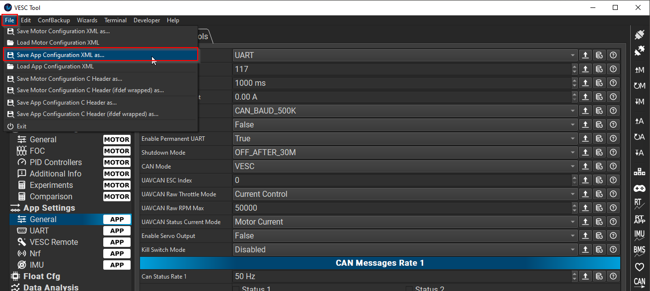
2. Choose a place to save the file on your computer and give it a meaningful name. I name my backups with the following format:
name-type-date.xml
For example, taking an app backup on my birthday, the filename would be: tk-app-feb03.xml

Install the Float Package
Take a breath. Prepare a celebratory beer. We’re in the home stretch.
1. Verify that your board is turned on and your are connected with VESC Tool from your desktop.
2. From the left menu bar, navigate to VESC Packages. Click the “Update Archive” button.

3. Under “Applications”, highlight “Float” and click the “Install to VESC” button.

4. Wait for the package to install and then click “OK”.


5. Disconnect and reconnect to your VESC using the quick disconnect and quick connect buttons.

6. Wait at least 10-15 seconds and you should see “Float Cfg” as new option in the left menu bar. If it does not appear, disconnect and reconnect again. If it still doesn’t appear, try to reinstall the Float package. When you can see “Float Cfg” in the left menu bar, continue on.

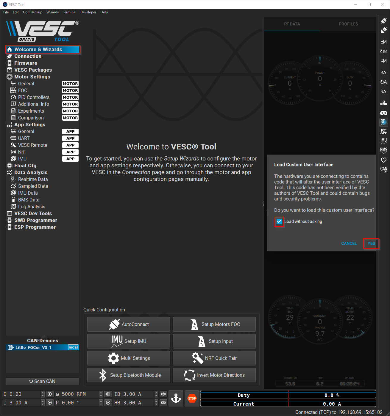
7. From the left menu bar, navigate to Welcome & Wizards. Check the box and click “Yes” to allow the new Float package App UI to load.
8. The Float package comes with a rideable configuration, so you don’t need to do anything else with it until you’re ready to tune your board to your liking.
References
The First Ride
Before you ride off into the sunset, let’s test to make sure the wheel is spinning in the right direction.
1. Support your onewheel from either side on a stable surface so that the tire is not touching anything. I recommend using a couple of chairs, sturdy boxes, or milk crates. Alternatively, you can hold the board in your hand or set it in your lap. Just make sure that the tire is not touching anything.
2. With the board turned on, engage both zones of the front footpad. The wheel should spin forward when the nose is tilted down, with the top of the tire moving towards the front of the board. If it’s spinning in the wrong direction:
a. From the left menu bar, navigate to Motor Settings > General.
b. Change the value of “Invert Motor Direction”.
c. Click the “Write Motor Config” button to save your changes.
3. Once you’ve verified that the motor is spinning in the right direction…
Ride It.
That’s it for the build process! If something has gone wrong along the way, see Troubleshooting Common Issues. If I haven’t answered your questions in this guide, start poking around on pev.dev, Discord, and Facebook.
I’ll be back soon with more troubleshooting steps, ride tuning, FAQs, upgrades and glossary terms.
If you have any questions or suggestions, shoot me an email at tk@spinningmag.net or find me on Instragram: @tkgarrett.
Glossary
AWG - American Wire Gauge. Shorthand notation when writing about wire gauges.
BMS - Battery Management System. It’s the circuit board that is connected directly to your battery pack. It’s responsible for maintaining the health of your battery, which it does by balancing the voltage - or charge level - of the individual cells of the battery pack. The voltage of the individual cells will drift apart over time if they are not managed. This will eventually lead to a battery fire while charging. That is why we DO NOT RECOMMEND running a onewheel without a BMS. When the BMS is connected to the stock Future Motion controller, it also does other things like monitor battery temperature levels and manage battery discharge.
Connector Types - JST, Molex (3 pin white, 6 pin black, and 16 pin black), Switchcraft, XLR, XT60


Hall Sensors - Within the hub, the hall effect sensors detect the position of the magnets and allow the VESC to know when and how much power to send to the motor.
IMU - Inertial Measurement Unit. Uses accelerometers and gyroscopes to detect the angle of the board. The VESC balance app uses this data to know how to adjust the amount of power it needs to send to the hub motor in order to keep the onewheel balanced.
PID - PID stands for “proportional–integral–derivative”. This is a type of software control loop that continuously takes feedback and adjusts the system it is controlling. In our case, the PID loop takes the input of the rider on the board and spins the wheel so that you stay upright. PID loops are explained in this video in a way that I can almost understand.
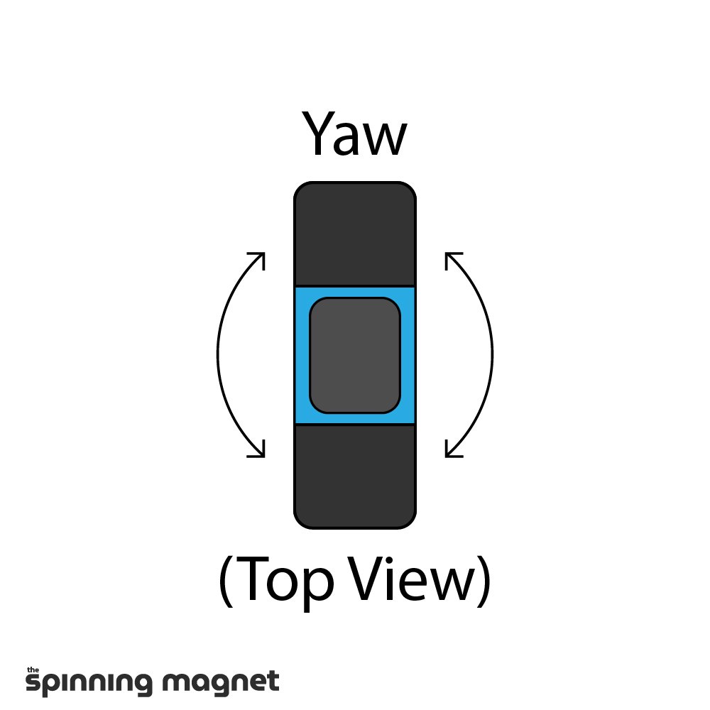
Roll, Pitch, and Yaw - The three dimensions of rotation detected by the IMU.

VESC - Vedder Electronic Speed Controller. Electronic Speed Controllers (ESC) are used in everything from drones to e-skates. VESC is an open-sourced ESC developed and trademarked by Benjamin Vedder. In the context of this project, we will be replacing the proprietary Future Motion ESC with a Little FOCer, which is a type of VESC. Read more at vesc-project.com.
VESC Packages - A feature that was added in VESC firmware version 6.0. The packages feature allows developers to extend the functionality of the VESC firmware without having to modify the firmware itself. For VESC onewheels, we are most interested in the Float package.
VESC Tool - VESC Tool is the open-source companion application for the VESC platform. Update firmware, change settings, check battery and other stats, all from the app. Available on iOS, Android, Mac, Windows, and Linux.
Wiring Harness - A wiring harness is a generic term for a bundle that contains multiple wires in bound together and typically wrapped in some sort of protective shroud. In the context of this guide, I’ll usually be referring to the wiring harness that is attached to the battery module and connects to the controller module using a 16 pin Molex.